⬇ Download Markdown · ⬇ Download LaTeX · ⬇ original · view original · CSV: table 1
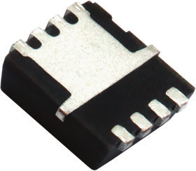
ORDERING INFORMATION Package Lead (Pb)-free and halogen-free PowerPAK 1212-8 SiSA40DN-T1-GE3
ABSOLUTE MAXIMUM RATINGS (T A = 25 °C, unless otherwise noted) PARAMETER Drain-source voltage Gate-source voltage Continuous drain current (T J = 150 °C)
SYMBOL
V DS V GS
Pulsed drain current (t = 100 μs)
I D I DM Continuous source-drain diode current T C = 25 °C T
A = 25 °C I S
Single pulse avalanche current Single pulse avalanche energy L = 0.1 mH I AS E AS T C = 25 °C T C = 70 °C Maximum power dissipation
T A = 25 °C T A = 70 °C Operating junction and storage temperature range Soldering recommendations (peak temperature) c I P T J , T stg LIMIT
20 +12 / -8
162 129 43.7 b, c 35 b, c 150 47 3.3 b, c
20 20 52 33 3.7 b, c 2.4 b, c -55 to +150
260 UNIT
VA mJ W °C THERMAL RESISTANCE RATINGS PARAMETER SYMBOL TYPICAL MAXIMUM UNIT t 10 s R thJA 24 33 Maximum junction-to-ambient b °C/W Maximum junction-to-case (drain) Steady state R thJF 1.9 2.4 Notes a. Package limited b. Surface mounted on 1" x 1" FR4 board c. t = 10 s d. See solder profile (www.vishay.com/doc?73257). The PowerPAK 1212-8 is a leadless package. The end of the lead terminal is exposed
copper (not plated) as a result of the singulation process in manufacturing. A solder fillet at the exposed copper tip cannot be guaranteed and is not required to ensure adequate bottom side solder interconnection e. Rework conditions: manual soldering with a soldering iron is not recommended for leadless components f. Maximum under steady state conditions is 81 °C/W
S18-0644-Rev. A, 25-Jun-2018 Document Number: 76681 1
For technical questions, contact: [email protected] THIS DOCUMENT IS SUBJECT TO CHANGE WITHOUT NOTICE. THE PRODUCTS DESCRIBED HEREIN AND THIS DOCUMENT
ARE SUBJECT TO SPECIFIC DISCLAIMERS, SET FORTH AT www.vishay.com/doc?91000
SPECIFICATIONS (T J = 25 °C, unless otherwise noted) PARAMETER SYMBOL TEST CONDITIONS MIN. TYP. MAX. UNIT V Static
V DS temperature coefficient Drain-source breakdown voltage
V GS(th) temperature coefficient V GS(th) /T J I D = 250 μA - -3.6 - mV/°C Gate-source threshold voltage V GS(th) V DS = V GS , I D = 250 μA 0.6 - 1.5 V Gate-source leakage I GSS V DS = 0 V, V GS = +12 / -8 V - - 100 nA
Zero gate voltage drain current I DSS
On-state drain current a Drain-source on-state resistance a Forward transconductance a
pF nC ns Drain-Source Body Diode Characteristics Continuous source-drain diode current I S Pulse diode forward current I SM Body diode voltage V SD Body diode reverse recovery time t rr Body diode reverse recovery charge Q rr Reverse recovery fall time t a Reverse recovery rise time t b
S18-0644-Rev. A, 25-Jun-2018 Document Number: 76681 2
For technical questions, contact: [email protected] THIS DOCUMENT IS SUBJECT TO CHANGE WITHOUT NOTICE. THE PRODUCTS DESCRIBED HEREIN AND THIS DOCUMENT
ARE SUBJECT TO SPECIFIC DISCLAIMERS, SET FORTH AT www.vishay.com/doc?91000
TYPICAL CHARACTERISTICS (25 °C, unless otherwise noted)
150 100
120 Current (A)
2nd line I D - Drain Current (A)
80 90
Output Characteristics Transfer Characteristics Axis Title 4 Axis Title 0.010 10 000 10000 10000 V GS = 2.5 V 0.004
100
0
18 36 54 72 1000 C rss
100 100 10 10 0 C oss 1000 1st line
2nd line 1000 0.006 2nd line C - Capacitance (pF)
0.008 1st line
2nd line 2nd line On-Resistance (Ω)
C iss 90 10 0 4 8 16 I D - Drain Current (A)
2nd line V DS - Drain-to-Source Voltage (V)
2nd line
On-Resistance vs. Drain Current and Gate Voltage Capacitance 1.7 1000 1st line
2nd line 6 4
2 0 10
8 16 24 32 40 10000 1.5
1000 1.3 1st line
2nd line I D = 10 A 8 2nd line R DS(on)
10000 0 20 Axis Title Axis Title 10 2nd line V GS - Gate-to-Source Voltage (V)
12 1.1
0.9 0.7 10
-50 -25 0 25 50 75 100 125 150 Q g - Total Gate Charge (nC)
2nd line T J - Junction Temperature (°C)
2nd line
Gate Charge On-Resistance vs. Junction Temperature S18-0644-Rev. A, 25-Jun-2018 100 Document Number: 76681 3 For technical questions, contact: [email protected] THIS DOCUMENT IS SUBJECT TO CHANGE WITHOUT NOTICE. THE PRODUCTS DESCRIBED HEREIN AND THIS DOCUMENT
ARE SUBJECT TO SPECIFIC DISCLAIMERS, SET FORTH AT www.vishay.com/doc?91000
TYPICAL CHARACTERISTICS (25 °C, unless otherwise noted)
Axis Title Axis Title
10000 0.2 1000
T J = 150 °C 1 T
J = 25 °C 100 -0.4
100 0.1
-0.7 0.01
0.2 0.4 0.6 0.8 I D = 250 μA -1.0 10 0 10 -50 1.0 -25 0 25 75 100 125 150
T J - Temperature (°C)
2nd line
Source-Drain Diode Forward Voltage Threshold Voltage Axis Title Axis Title 0.005 10000 150 10000
1000 2nd line
Power (W)
1000 T J = 150 °C 0.002 90 1st line
2nd line 0.003
1st line
2nd line 2nd line R DS(on)
50 V SD - Source-to-Drain Voltage (V)
2nd line 0.004
1st line
2nd line 2nd line V GS(th)
2nd line 2nd line I S - Source Current (A)
0.5 10000 100 60 100 100 0.001 30
T J = 25 °C
0 10
0 2 4 6 8 0 0.001 10 10 0.01 0.1 1 10 V GS - Gate-to-Source Voltage (V)
2nd line Time (s) 2nd line On-Resistance vs. Gate-to-Source Voltage Single Pulse Power, Junction-to-Ambient Axis Title 1000 10000 I DM limited I D limited 100 μs
1000 10 1st line
2nd line 2nd line I D - Drain Current (A)
100 1 ms Limited by R DS(on) (1) 10 ms 1 100 ms
100 1s 10s 0.1
DC T A = 25 °C Single pulse 0.01
0.01 (1) V BVDSS limited
10 0.1 1 10 100 V DS - Drain-to-Source Voltage (V) GS > minimum V GS at which R DS(on) is specified
Safe Operating Area, Junction-to-Ambient S18-0644-Rev. A, 25-Jun-2018 Document Number: 76681 4
For technical questions, contact: [email protected] THIS DOCUMENT IS SUBJECT TO CHANGE WITHOUT NOTICE. THE PRODUCTS DESCRIBED HEREIN AND THIS DOCUMENT
ARE SUBJECT TO SPECIFIC DISCLAIMERS, SET FORTH AT www.vishay.com/doc?91000
TYPICAL CHARACTERISTICS (25 °C, unless otherwise noted)
Axis Title 200 10000 1000 120 1st line
2nd line 2nd line I D - Drain Current (A)
160 80
100 40 0 10
0 25 50 75 100 125 150
T C - Case Temperature (°C)
2nd line
Current Derating a Axis Title Axis Title 65 10000 2.0 52 10000 1.6 1.2 1st line
2nd line 26 2nd line
Power (W)
1000 1st line
2nd line 2nd line
Power (W)
1000 39 0.8 100 13 100 0.4 0 10
0 25 50 75 100 125 150 0 10
0 25 50 75 100 125 T C - Case Temperature (°C)
2nd line T A - Ambient Temperature (°C)
2nd line
Power, Junction-to-Case Power, Junction-to-Ambient 150 Note a. The power dissipation P D is based on T J max. = 150 °C, using junction-to-case thermal resistance, and is more useful in settling the upper
dissipation limit for cases where additional heatsinking is used. It is used to determine the current rating, when this rating falls below the package limit S18-0644-Rev. A, 25-Jun-2018 Document Number: 76681 5
For technical questions, contact: [email protected] THIS DOCUMENT IS SUBJECT TO CHANGE WITHOUT NOTICE. THE PRODUCTS DESCRIBED HEREIN AND THIS DOCUMENT
ARE SUBJECT TO SPECIFIC DISCLAIMERS, SET FORTH AT www.vishay.com/doc?91000
TYPICAL CHARACTERISTICS (25 °C, unless otherwise noted)
Axis Title
10000 Duty Cycle = 0.5 Notes: 0.2 1000 1st line
2nd line Normalized Effective Transient Thermal Impedance 1 P DM 0.1 0.1
0.05 0.02
Single pulse 0.01
0.0001 0.001 0.01 100
0.1 1 10 100 10 1000 Square Wave Pulse Duration (s)
2nd line
Normalized Thermal Transient Impedance, Junction-to-Ambient Axis Title 1 10000 0.2 0.1
1000 0.05 0.1 1st line 2nd
line Normalized Effective Transient Thermal Impedance Duty Cycle = 0.5 0.02 100 Single pulse 0.01
0.0001 10 0.001 0.01 0.1 1 10
Square Wave Pulse Duration (s)
2nd line
Normalized Thermal Transient Impedance, Junction-to-Case Vishay Siliconix maintains worldwide manufacturing capability. Products may be manufactured at one of several qualified locations. Reliability data for Silicon Technology and Package Reliability represent a composite of all qualified locations. For related documents such as package / tape drawings, part marking, and reliability data, see www.vishay.com/ppg?76681.
S18-0644-Rev. A, 25-Jun-2018 Document Number: 76681 6
For technical questions, contact: [email protected] THIS DOCUMENT IS SUBJECT TO CHANGE WITHOUT NOTICE. THE PRODUCTS DESCRIBED HEREIN AND THIS DOCUMENT
ARE SUBJECT TO SPECIFIC DISCLAIMERS, SET FORTH AT www.vishay.com/doc?91000
D4
WH E2
E4 L K M θ e 1
Z
D5 D D2 2 2 D1 8 1 5 4
θ 4 b 3 L1 E3
A1 Backside view of single pad H 2 E1 E Detail Z L K E2 E4 D2 D3(2x)
D4 c A H 1 D1
2 K1 Notes 1. Inch will govern 2 Dimensions exclusive of mold gate burrs
D2 3 4 b θ D5 θ E3 Backside view of dual pad DIM.
MILLIMETERS INCHES MIN. NOM. MAX. MIN. NOM. MAX. A 0.97 1.04 1.12 0.038 0.041 0.044 A1 0.00 - 0.05 0.000 - 0.002 b 0.23 0.30 0.41 0.009 0.012 0.016 c 0.23 0.28 0.33 0.009 0.011 0.013 D 3.20 3.30 3.40 0.126 0.130 0.134 D1 2.95 3.05 3.15 0.116 0.120 0.124 D2 1.98 2.11 2.24 0.078 0.083 0.088 D3 0.48 - 0.89 0.019 - 0.035 D4 0.47 typ. D5 2.3 typ.
0.0185 typ 0.090 typ E 3.20 3.30 3.40 0.126 0.130 0.134 E1 2.95 3.05 3.15 0.116 0.120 0.124 E2 1.47 1.60 1.73 0.058 0.063 0.068 E3 1.75 1.85 1.98 0.069 0.073 0.078 E4 0.034 typ. 0.013 typ. e 0.65 BSC 0.026 BSC K 0.86 typ. K1 0.35 - 0.034 typ. - 0.014 - - H 0.30 0.41 0.51 0.012 0.016 0.020 L 0.30 0.43 0.56 0.012 0.017 0.022 L1 0.06 0.13 0.20 0.002 0.005 0.008 0° - 12° 0° - 12° W 0.15 0.25 0.36 0.006 0.010 0.014 M 0.125 typ. 0.005 typ. ECN: S16-2667-Rev. M, 09-Jan-17 DWG: 5882 Revison: 09-Jan-17 Document Number: 71656 1
For technical questions, contact: [email protected] THIS DOCUMENT IS SUBJECT TO CHANGE WITHOUT NOTICE. THE PRODUCTS DESCRIBED HEREIN AND THIS DOCUMENT
ARE SUBJECT TO SPECIFIC DISCLAIMERS, SET FORTH AT www.vishay.com/doc?91000
RECOMMENDED MINIMUM PADS FOR PowerPAK ® 1212-8 Single 0.152
(3.860)
0.039 0.068
(0.990) (1.725)
0.010 (0.255)
(2.390) 0.094 0.088 (2.235)
0.016 (0.405)
0.026 (0.660)
0.025 0.030
(0.635) (0.760)
Recommended Minimum Pads Dimensions in Inches/(mm)
Return to Index Return to Index
Document Number: 72597 Revision: 21-Jan-08 www.vishay.com
7
www.vishay.com Vishay
ALL PRODUCT, PRODUCT SPECIFICATIONS AND DATA ARE SUBJECT TO CHANGE WITHOUT NOTICE TO IMPROVE RELIABILITY, FUNCTION OR DESIGN OR OTHERWISE.
Vishay Intertechnology, Inc., its affiliates, agents, and employees, and all persons acting on its or their behalf (collectively, “Vishay”), disclaim any and all liability for any errors, inaccuracies or incompleteness contained in any datasheet or in any other disclosure relating to any product.
Vishay makes no warranty, representation or guarantee regarding the suitability of the products for any particular purpose or the continuing production of any product. To the maximum extent permitted by applicable law, Vishay disclaims (i) any and all liability arising out of the application or use of any product, (ii) any and all liability, including without limitation special, consequential or incidental damages, and (iii) any and all implied warranties, including warranties of fitness for particular purpose, non-infringement and merchantability.
Statements regarding the suitability of products for certain types of applications are based on Vishay's knowledge of typical requirements that are often placed on Vishay products in generic applications. Such statements are not binding statements about the suitability of products for a particular application. It is the customer's responsibility to validate that a particular product with the properties described in the product specification is suitable for use in a particular application. Parameters provided in datasheets and / or specifications may vary in different applications and performance may vary over time. All operating parameters, including typical parameters, must be validated for each customer application by the customer's technical experts. Product specifications do not expand or otherwise modify Vishay's terms and conditions of purchase, including but not limited to the warranty expressed therein.
Hyperlinks included in this datasheet may direct users to third-party websites. These links are provided as a convenience and for informational purposes only. Inclusion of these hyperlinks does not constitute an endorsement or an approval by Vishay of any of the products, services or opinions of the corporation, organization or individual associated with the third-party website. Vishay disclaims any and all liability and bears no responsibility for the accuracy, legality or content of the third-party website or for that of subsequent links.
Vishay products are not designed for use in life-saving or life-sustaining applications or any application in which the failure of the Vishay product could result in personal injury or death unless specifically qualified in writing by Vishay. Customers using or selling Vishay products not expressly indicated for use in such applications do so at their own risk. Please contact authorized Vishay personnel to obtain written terms and conditions regarding products designed for such applications.
No license, express or implied, by estoppel or otherwise, to any intellectual property rights is granted by this document or by any conduct of Vishay. Product names and markings noted herein may be trademarks of their respective owners.
© 2026 VISHAY INTERTECHNOLOGY, INC. ALL RIGHTS RESERVED
Revision: 01-Jan-2026 1 Document Number: 91000 THIS DOCUMENT IS SUBJECT TO CHANGE WITHOUT NOTICE. THE PRODUCTS DESCRIBED HEREIN AND THIS DOCUMENT
ARE SUBJECT TO SPECIFIC DISCLAIMERS, SET FORTH AT www.vishay.com/doc?91000