
⬇ Download Markdown · ⬇ Download LaTeX · ⬇ original · view original · CSV: table 1, table 2, table 3, table 4, table 5, table 6, table 7, table 8, table 9, table 10, table 11, table 12, table 13, table 14, table 15, table 16, table 17, table 18, table 19
[AK5522]
The AK5522 is a 32-bit, from 8kHz to 192kHz sampling A/D converter for line and microphone inputs of digital audio systems. It achieves 108dB dynamic range and 98dB S/(N+D) while keeping low power consumption performance. Four types of digital filters are integrated and selectable according to the sound quality preference. The AK5522 has great power supply rejection ratio, (PSRR), and common mode rejection ratio, (CMRR), enabling to maintain sufficient characteristics when connecting USB bus power or DCDC converter output as a power supply. It is suitable for applications with noisy power supply such as USB audio interface, wireless speakers and car audio equipment. In addition, the AK5522 integrates a regulator with high PSRR for DAC power supply. Using the AK5522 with a DAC such as the AK4432 or the AK4452, it is enable to bring maximum DAC performance even in a poor power supply condition. Moreover, the AK5522 integrates low-jitter PLL circuit that generates a master clock for DAC from LRCK or BICK. It provides a low-EMI solution by avoiding unnecessary drawing of the master clock that has high frequency, on the board. The AK5522 helps reducing components and a mounting space with these features for environmental noise.
Sampling Rate: 8kHz - 192kHz Input: Full Differntial, Pseudo Differential, Single-Ended S/(N+D): 98dB typ. DR, S/N: 108dB typ. PSRR: 80dB typ. CMRR: 80dB typ. Internal Filter: Four types of LPF, Digital HPF Short Group Delay: 4.4/fs (Short Delay Slow roll-off) Output Format: 32-bit MSB justified, I 2 S or TDM (Cascade Connection available) Operation Mode: Master or Slave Modes Programmable Gain Amp: 3dB - +12dB/1dB (Fixed at 0dB in Parallel Control mode) Integrated PLL: Generates the master clock from BICK or LRCK Master Clock Output: Output master clock generated by the PLL Voltage Regulator for External DAC Power: Generates 3.3V from 5V applied to AVDD pin. Power Supply: Analog 4.5 - 5.5V or 3.0 - 3.6V, Digital 3.0 - 3.6V or 1.7 - 1.98V Control Mode: Parallel Control mode (Pin setting)
Serial Control mode (I 2 C Bus setting)
Operation Temperature: 40 - 105C Package: 24-pin QFN 4mmx4mm, 0.5mm pitch 017002311-E-00 2017/03
General Description ............................................................................................................................ 1 Features .............................................................................................................................................. 1 Table of Contents ................................................................................................................................ 2 Block Diagram ..................................................................................................................................... 4 ■ Block Diagram.................................................................................................................................... 4 5. Pin Configurations and Functions ...................................................................................................... 4
■ Pin Configurations ............................................................................................................................. 4 ■ Pin Functions ..................................................................................................................................... 5 ■ Handling of Unused Pin ..................................................................................................................... 6 6. Absolute Maximum Ratings ................................................................................................................ 7 7. Recommended Operation Conditions ................................................................................................ 7 8. Analog Characteristics ........................................................................................................................ 8
■ Analog Power Supply=5.0V ............................................................................................................... 8 ■ Analog Power Supply=3.3V ............................................................................................................... 9 9. Filter Characteristics ......................................................................................................................... 10
■ ADC Filter Characteristics (fs= 48kHz) ........................................................................................... 10 ■ ADC Filter Characteristics (fs= 96kHz) ........................................................................................... 12 ■ ADC Filter Characteristics (fs= 192kHz) ......................................................................................... 14 10. DC Characteristics ........................................................................................................................ 16 11. Switching Characteristics (Parallel Control Mode) ....................................................................... 17
■ System Clocks ................................................................................................................................. 17 ■ Audio Interface ................................................................................................................................. 21 ■ Power-down, Reset (Parallel Control Mode) ................................................................................... 22 ■ Timing Diagram (Parallel Control Mode) ......................................................................................... 22 12. Switching Characteristics (Serial Control Mode) .......................................................................... 25
■ System Clocks ................................................................................................................................. 25 ■ Audio Interface ................................................................................................................................. 32 ■ I 2 C Bus, Power-down, Reset (Serial Control Mode) ....................................................................... 34 ■ Timing Diagram (Serial Control Mode) ............................................................................................ 35 13. Functional Descriptions (Parallel Control Mode) .......................................................................... 40
■ Digital Power Supply ........................................................................................................................ 40 ■ Analog Power Supply ...................................................................................................................... 40 ■ Regulator for External DAC Power Supply ..................................................................................... 40 ■ Parallel / Serial Control Mode .......................................................................................................... 40 ■ System Clocks (Parallel Control Mode) .......................................................................................... 40 ■ Operation Mode (Parallel Control Mode)......................................................................................... 42 ■ Audio Interface Format (Parallel Control Mode) ............................................................................. 46 ■ Cascade Connection in TDM Mode (Parallel Control Mode) .......................................................... 46 ■ Digital HPF (Parallel Control Mode) ................................................................................................ 49 ■ Digital Filter Setting (Parallel Control Mode) ................................................................................... 49 ■ Input Gain (Parallel Control Mode) .................................................................................................. 49 ■ Power-up Function/ Sequence (Parallel Control Mode) ................................................................. 49 ■ Power Down Function/ Sequence ................................................................................................... 52 14. Functional Descriptions (Serial Control Mode) ............................................................................. 53
■ Digital Power Supply ........................................................................................................................ 53 ■ Analog Power Supply ...................................................................................................................... 53 ■ Regulator for External DAC Power Supply ..................................................................................... 53 ■ Parallel / Serial Control Mode .......................................................................................................... 53 ■ System Clocks (Serial Control Mode) ............................................................................................. 53 ■ Audio Interface Format (Serial Control Mode) ................................................................................ 62 ■ Cascade Connection in TDM Mode (Serial Control Mode) ............................................................. 62 1. 2. 3. 4.
017002311-E-00 2017/03
■ Outline Dimensions .......................................................................................................................... 82 ■ Material & Lead Finish ..................................................................................................................... 82 ■ Marking ............................................................................................................................................ 82 17. Ordering Guide .............................................................................................................................. 83
■ Ordering Guide ................................................................................................................................ 83 18. Revision History ............................................................................................................................ 83 IMPORTANT NOTICE ........................................................................................................................... 84 017002311-E-00 2017/03
■ Block Diagram AVDD VREF REGAO LINP LINN REGDO DVSS LOOP 3.3V Regulator (for DAC)
5V or 3.3V AVSS DVDD Regulator (Digital)
3.3V or 1.8V PLL 1.8V
3dB ~ 12dB/ 1dB step + - AAF Delta-Sigma Modulator Decimation
Filter AAF Delta-Sigma Modulator Decimation Filter MCLK 1fs 64fs HPF Serial Output Interface BICK LRCK SDTO CKS3/SDA RINP RINN + - CKS2/SCL HPF
CKS1 CKS0/TDMI 3dB ~ 12dB/ 1dB step PDN SD DIF PSN Figure 1. Block Diagram
18 17 16 15 14 13 MCLK DVDD DVSS REGAO AVDD AVSS ■ Pin Configurations 19 20 21 22 23 24
12 11 10 9 8 7 LOOP VREF RINP RINN LINN LINP CKS3/SDA PDN CKS1 SD PSN DIF 1 2 3 4 5 6 REGDO
LRCK BICK SDTO CKS0/TDMI CKS2/SCL Figure 2. Pin Configurations 017002311-E-00 2017/03
| No. | Pin Name | I/O | Function | Power Down Status |
|---|---|---|---|---|
| 1 | CKS3 | I | Clock Mode Select Pin in Parallel Control mode | Hi-Z |
| 1 | SDA | IO | Control Data I/O Pin for I2 C Bus in Serial Control mode | Hi-Z |
| 2 | PDN | I | Reset and Power Down Pin | Hi-Z |
| 3 | CKS1 | I | Clock Mode Select Pin | Hi-Z |
| 4 | SD | I | Digital Filter Select Pin in Parallel Control mode “L”: Sharp Roll-Off, “H”: Short Delay Sharp Roll-Off | Hi-Z |
| 5 | PSN | I | Control Mode Select Pin “L”: Serial Control mode, “H”: Parallel Control mode | Hi-Z |
| 6 | DIF | I | Data Format Select Pin in Parallel Control mode “L”: MSB Justified, “H”: I2 S Compatible | Hi-Z |
| 7 | LINP | I | L Channel Positive Signal Input Pin | Hi-Z |
| 8 | LINN | I | L Channel Negative Signal Input Pin | Hi-Z |
| 9 | RINN | I | R Channel Negative Signal Input Pin | Hi-Z |
| 10 | RINP | I | R Channel Positive Signal Input Pin | Hi-Z |
| 11 | VREF | O | Internal Reference Voltage Decoupling Pin Decouple this pin to AVSS with a 1F50% capacitor. | Hi-Z, Pulled-down with 0.7k |
| 12 | LOOP | O | PLL Loop Filter Connect Pin Connect this pin to AVSS with a 0.01F50% capacitor. | Hi-Z |
| 13 | AVSS | P | Analog Ground Pin | - |
| 14 | AVDD | P | Analog Power Supply Pin. 3.0 -3.6V or 4.5 -5.5V | - |
| 15 | REGAO | O | Regulator for External DAC Output Pin AVDD=4.5V -5.5V: 3.3V typ. AVDD=3.0V -3.6V: Low (External capacitor is not necessary) Connect to AVSS with a 10F50% capacitor. Additionally, this pin must be decoupled to the power supply pin of an external DAC with a 10F50% and a 0.1F50% capacitors in parallel. ( Figure 81 , Figure 82 ) | Hi-Z, Pulled-down with 0.5k |
| 16 | DVSS | P | Digital Ground Pin | - |
| 17 | DVDD | P | Digital Power Supply Pin. 3.0 -3.6V | - |
| 18 | MCLK | I | Master Clock Input Pin in EXT Master / EXT Slave / PLL Master mode This pin is pulled-down to DVSS internally with a 100k resister. | Hi-Z (Input mode) |
| 18 | MCLK | O | Master Clock Output Pin in PLL Slave mode This pin is pulled-down to DVSS internally with a 100k resister. | Hi-Z (Input mode) |
| 19 | REGDO | O | Regulator Stabilization Capacitor Connect Pin DVDD=3.0V -3.6V: Output 1.8V typ. Connect to DVSS with a 1F50% capacitor. | Hi-Z |
| 19 | REGDO | I | DVDD=1.7V -1.98V: Connect to DVDD | - |
| 20 | LRCK | I | Channel Clock Input Pin in Slave mode This pin is pulled-down to DVSS internally with a 100k resister. | Hi-Z (Input mode) |
| 20 | LRCK | O | Channel Clock Output Pin in Master mode This pin is pulled-down to DVSS internally with a 100k resister. | Hi-Z (Input mode) |
| 21 | BICK | I | Audio Serial Data Clock Input Pin in Slave mode This pin is pulled-down to DVSS internally with a 100k resister. | Hi-Z (Input mode) |
| 21 | BICK | O | Audio Serial Data Clock Output Pin in Master mode This pin is pulled-down to DVSS internally with a 100k resister. | Hi-Z (Input mode) |
| 22 | SDTO | O | Audio Serial Data Output Pin | L |
| 23 | CKS0 | I | Clock Mode Select Pin in Parallel Control mode | Hi-Z |
| 23 | TDMI | I | TDM Data Input Pin in TDM mode | Hi-Z |
| 24 | CKS2 | I | Clock Mode Select Pin in Parallel Control mode | Hi-Z |
| 24 | SCL | I | Control Clock Input Pin for I2 C Bus in Serial Control mode | Hi-Z |
AVDD=3.0V - 3.6V: Low (External capacitor is not necessary) Connect to AVSS with a 10F50% capacitor. Additionally, this pin must be decoupled to the power supply pin of an external DAC with a 10F50% and a 0.1F50% capacitors in parallel. ( Figure 81 , Figure 82 ) Digital Ground Pin Digital Power Supply Pin. 3.0 - 3.6V Master Clock Input Pin in EXT Master / EXT Slave / PLL Master mode
This pin is pulled-down to DVSS internally with a 100k resister. Master Clock Output Pin in PLL Slave mode
This pin is pulled-down to DVSS internally with a 100k resister. Regulator Stabilization Capacitor Connect Pin
Connect to DVSS with a 1F50% capacitor. DVDD=1.7V - 1.98V: Connect to DVDD Channel Clock Input Pin in Slave mode
This pin is pulled-down to DVSS internally with a 100k resister. Channel Clock Output Pin in Master mode
This pin is pulled-down to DVSS internally with a 100k resister. Audio Serial Data Clock Input Pin in Slave mode
This pin is pulled-down to DVSS internally with a 100k resister. Audio Serial Data Clock Output Pin in Master mode
This pin is pulled-down to DVSS internally with a 100k resister. Audio Serial Data Output Pin Clock Mode Select Pin in Parallel Control mode TDM Data Input Pin in TDM mode Clock Mode Select Pin in Parallel Control mode 2 Control Clock Input Pin for I C Bus in Serial Control mode Power Down
Status Hi-Z Hi-Z Hi-Z Hi-Z Hi-Z Hi-Z Hi-Z
Hi-Z Hi-Z Hi-Z Hi-Z Hi-Z, Pulled-down with 0.7k
Hi-Z - - Hi-Z, Pulled-down with 0.5k - - Hi-Z (Input mode)
Hi-Z - Hi-Z (Input mode)
Hi-Z (Input mode)
LHi-Z Hi-Z Hi-Z Hi-Z I/O I: Input, O: Output, IO: Input and Output, P: Power Supply Note 1. All digital input pins must not be allowed to float.
017002311-E-00 2017/03
[AK5522] ■ Handling of Unused Pin The unused I/O pins should be connected appropriately.
| Classification | Pin Name | Setting |
|---|---|---|
| Analog | LINP, LINN, RINP, RINN | Open |
| Analog | REGAO (AVDD = 4.5V -5.5V, Regulator for DAC = Enable) | Decouple with a 10 F capacitor to AVSS |
| Analog | REGAO (AVDD = 4.5V -5.5V, Regulator for DAC = Disable) | Open |
| Analog | REGAO (AVDD = 3.0V -3.6V) | Open |
| Analog | LOOP | Open |
| Digital | CKS1, CKS0, SD, DIF (Serial Control mode) | Connect to DVSS |
| Digital | TDMI (TDM mode) | Connect to DVSS |
| Digital | MCLK (PLL Slave mode) | Open |
LOOP CKS1, CKS0, SD, DIF (Serial Control mode) TDMI (TDM mode) MCLK (PLL Slave mode)
017002311-E-00 Setting Open Decouple with a 10 F capacitor to AVSS Open Open Open Connect to DVSS Connect to DVSS Open 2017/03 - 6 - [AK5522]
Parameter Symbol Min. Analog (AVDD pin) VA −0.3 Power Digital (DVDD pin) VD −0.3 Supplies
Digital (REGDO pin) VRD −0.3 Input Current (Any Pin Except Supplies) IIN - Analog Input Voltage (LINP/N, RINP/N pins) VINA VDM−0.3 (Note 3) Digital Input Voltage (Note 5) VIND −0.3 Max. 6.0 6.0 2.5 10 VDP+0.3 or 6.0
(Note 4) VD+0.3 or 6.0
(Note 6)
105 150 Unit V V V mA
VV Ambient Temperature (Power applied) Ta −40 C Storage Temperature Tstg −65 C Note 2. All voltages with respect to ground. Note 3. VDM and VDP are the voltages generated internally. Note 4. The maximum value of input voltage is lower value between (VDP+0.3) V or 6.0 V. Note 5. PDN, SD, LRCK, BICK, MCLK, PSN, CKS0/TDMI, CKS1, CKS2/SCL, CKS3/SDA and DIF pins Note 6. The maximum value of input voltage is lower value between (VD+0.3) V or 6.0 V.
Mode Power-down Normal operation AVDD VDM 3.0 - 3.6V, 4.5 - 5.5V AVSS
4.5 - 5.5V −0.75V 3.0 - 3.6V −1.50V Table 1. VDM, VDP Voltage VDP AVDD 5.25V 4.50V WARNING: Operation at or beyond these limits may result in permanent damage to the device.
Normal operation is not guaranteed at these extremes.
Parameter Symbol Min. Typ. Max. Unit
Analog (AVDD) VA 4.5 5.0 5.5 V Analog (AVDD) VA 3.0 3.3 3.6 V Power Using internal regulator Supplies
Digital (DVDD) VD 3.0 3.3 3.6 V Not using internal regulator Digital (DVDD) VD 1.7 1.8 1.98 V Digital (REGDO) VRD Note 2. All voltages with respect to ground. Note 7. The power up sequence between AVDD and DVDD is not critical. If DVDD is 1.7V to 1.98V then
the DVDD pin should be connect to the REGDO pin.
017002311-E-00 2017/03
■ Analog Power Supply=5.0V
32-bit Data; Measurement frequency=20Hz - 20kHz at fs=48kHz, 40Hz - 40kHz at fs=96kHz and 192kHz, Gain=0dB, unless otherwise specified.) Parameter Min. Typ. Max. Unit Analog Input Characteristics: Resolution (Note 8) - - 32 Bit Input Voltage 2.0 2.1 2.2 Vrms
Dynamic Range 103 108 - dB fs=48kHz, BW=20kHz (60dBFS with A-weighted) Dynamic Range (60dBFS) fs=96kHz, 192kHz, BW=40kHz 98 103 - dB
Input Resistance Gain= +12dB 5 8.5 - k
Full Differential 0dB 10 20.7 - k
3dB 10 23.8 - k Gain= +12dB 5 14.0 - k Pseudo Differential 0dB 10 27.3 - k Single End
3dB 10 30.3 - k Interchannel Isolation 110 120 dB Interchannel Gain Mismatch - 0 0.5 dB Power Supply Rejection Ratio (PSRR) (Note 9) - 80 - dB Common Mode Rejection Ratio (CMRR) 55 80 - dB VREF pin Output Voltage 3.72 3.92 4.12 V Regulator for External DAC Output Voltage 3.0 3.3 3.6 V Output Current - - 15 mA Power Supply Rejection Ratio (Note 9) - 80 - dB Output Noise (Flat) - 101 - dBV Power Supplies Power Supply Current
Normal Operation (PDN pin = “H”) (Note 10)
Power down mode (PDN pin = “L”) (Note 11)
AVDD+DVDD - 0 10 A Note 8. ADC full-scale input voltage at Gain=0dB. The signal input amplitude can’t exceed 2.1Vrms (typ.)
even if the gain is from 3dB to 1dB. Note 9. PSRR is applied to AVDD, DVDD with 20Hz - 20kHz sine wave. Note 10. PLL Master mode. PLL3-0 bits = “0101b” Note 11. All digital inputs are fixed to DVDD or DVSS.
017002311-E-00 2017/03
Data; Measurement frequency=20Hz - 20kHz at fs=48kHz, 40Hz - 40kHz at fs=96kHz and 192kHz, Gain=0dB, unless otherwise specified.) Parameter Min. Typ. Max. Unit Analog Input Characteristics: Resolution - - 32 Bit Input Voltage (Note 8) 2.0 2.1 2.2 Vrms
Dynamic Range 99 104 - dB fs=48kHz, BW=20kHz (60dBFS with A-weighted) Dynamic Range (60dBFS) fs=96kHz, 192kHz, BW=40kHz 94 99 - dB
Input Resistance Gain= +12dB 5 12.0 - k
Full Differential 0dB 10 25.2 - k
3dB 10 29.4 - k Gain= +12dB 5 18.4 - k Pseudo Differential 0dB 10 30.9 - k Single End
3dB 10 32.4 - k Interchannel Isolation 110 120 dB
Interchannel Gain Mismatch - 0 0.5 dB Power Supply Rejection Ratio (Note 9) - 80 - dB Common Mode Rejection Ratio (CMRR) 55 80 - dB VREF pin Output Voltage 2.34 2.47 2.60 V Power Supplies Power Supply Current
Normal Operation (PDN pin = “H”) (Note 10)
Power down mode (PDN pin = “L”) (Note 11)
AVDD+DVDD - 0 10 A Note 8. ADC full-scale input voltage at Gain=0dB. The signal input amplitude can’t exceed 2.1Vrms (typ.)
even if the gain is from 3dB to 1dB. Note 9. PSRR is applied to AVDD, DVDD with 20Hz - 20kHz sine wave. Note 10. PLL Master mode. PLL3-0 bits = “0101b” Note 11. All digital inputs are fixed to DVDD or DVSS.
017002311-E-00 2017/03
■ ADC Filter Characteristics (fs= 48kHz)
Parameter Symbol Min. Typ. Max. Unit Digital Filter (Decimation LPF): SHARP ROLL-OFF (Figure 3) (Parallel Control mode: SD pin=“L”, Serial Control mode: SD bit=”0”, SLOW bit=”0”) Passband (Note 12) PB 0 - kHz 22.0 +0.001/0.06dB
21.9 - kHz 6.0dB Stopband (Note 12) SB 36.5 - - kHz Stopband Attenuation SA 85 - - dB Group Delay Distortion 0 - 20.0kHz - 0 - 1/fs GD Group Delay (Note 13) GD - 6.7 - 1/fs Digital Filter (Decimation LPF): SHORT DELAY SHARP ROLL-OFF FILTER (Figure 5) (Parallel Control mode: SD pin=”H”, Serial Control mode: SD bit=”1”, SLOW bit=”0”) Passband (Note 12) PB 0 - 22.0 kHz +0.001/0.06dB
24.4 - kHz 6.0dB Stopband (Note 12) SB 27.9 - - kHz Stopband Attenuation SA 85 - - dB Group Delay Distortion 0 - 20.0kHz - - 2.8 1/fs GD Group Delay (Note 13) GD - - 1/fs 4.9 Digital Filter (Decimation LPF): SHORT DELAY SLOW ROLL-OFF (Figure 6) (Parallel Control mode: Not Available, Serial Control mode: SD bit=”1”, SLOW bit=”1”) Passband (Note 12) +0.001/0.076dB PB 0 - 12.5 kHz
FR - 2.5 - Hz 0.5dB (Note 12) - 6.5 - Hz 0.1dB Note 12. The passband and stopband frequencies scale with fs.
Note 13. The calculated delay time induced by digital filtering. This time is from the input of an analog
signal to the L channel MSB output timing of the SDTO. It may have an error of +1[1/fs] at maximum when outputting data via audio interfaces. The signal frequency is 1kHz.
017002311-E-00 2017/03
[AK5522]
017002311-E-00 2017/03
Parameter Symbol Min. Typ. Max. Unit Digital Filter (Decimation LPF): SHARP ROLL-OFF (Figure 7) (Parallel Control mode: SD pin=“L”, Serial Control mode: SD bit=”0”, SLOW bit=”0”) 44.1 Passband (Note 12) +0.001/0.06dB 0 - kHz PB
48.8 kHz 6.0dB Stopband (Note 12) SB 55.7 - - kHz Stopband Attenuation SA 85 - - dB Group Delay Distortion 0 - 40.0kHz - 0 - 1/fs GD Group Delay (Note 13) GD - - 1/fs 18.8 Digital Filter (Decimation LPF): SLOW ROLL-OFF (Figure 8) (Parallel Control mode: Not Available, Serial Control mode: SD bit=”0”, SLOW bit=”1”) 25 Passband (Note 12) +0.001/0.076dB 0 - kHz PB
43.8 kHz 6.0dB Stopband (Note 12) SB 73 - - kHz Stopband Attenuation SA 85 - - dB Group Delay Distortion 0 - 40.0kHz - 0 - 1/fs GD Group Delay (Note 13) GD - - 1/fs 6.7 Digital Filter (Decimation LPF): SHORT DELAY SHARP ROLL-OFF (Figure 9) (Parallel Control mode: SD pin=”H”, Serial Control mode: SD bit=”1”, SLOW bit=”0”) Passband (Note 12) 0 - 44.1 kHz +0.001/0.06dB PB
48.8 - kHz 6.0dB Stopband (Note 12) SB 55.7 - - kHz Stopband Attenuation SA 85 - - dB Group Delay Distortion 0 - 40.0kHz - - 2.8 1/fs GD Group Delay (Note 13) GD - - 1/fs 4.9 Digital Filter (Decimation LPF): SHORT DELAY SLOW ROLL-OFF (Figure 10) (Parallel Control mode: Not Available, Serial Control mode: SD bit=”1”, SLOW bit=”1”) Passband (Note 12) 0 - 25 kHz +0.001/0.076dB PB
43.8 - kHz 6.0dB Stopband (Note 12) SB 73 - - kHz Stopband Attenuation SA 85 - - dB Group Delay Distortion 0 - 40.0kHz - - 1.2 1/fs GD Group Delay (Note 13) GD - - 1/fs 4.4 Digital Filter (HPF): 3.0dB Frequency Response - 1.0 - Hz
FR - 2.5 - Hz 0.5dB (Note 12) - 6.5 - Hz 0.1dB Note 12. The passband and stopband frequencies scale with fs.
Note 13. The calculated delay time induced by digital filtering. This time is from the input of an analog
signal to the L channel MSB output timing of the SDTO. It may have an error of +1[1/fs] at maximum when outputting data via audio interfaces. The signal frequency is 1kHz.
017002311-E-00 2017/03
017002311-E-00 2017/03
Parameter Symbol Min. Typ. Max. Unit Digital Filter (Decimation LPF): SHARP ROLL-OFF (Figure 11) (Parallel Control mode: SD pin=“L”, Serial Control mode: SD bit=”0”, SLOW bit=”0”) 83.7 Passband (Note 12) +0.001/0.037dB 0 - kHz PB
100.2 kHz 6.0dB Stopband (Note 12) SB 122.9 - - kHz Stopband Attenuation SA 85 - - dB Group Delay Distortion 0 - 40.0kHz - 0 - 1/fs GD Group Delay (Note 13) GD - - 1/fs 14.9 Digital Filter (Decimation LPF): SLOW ROLL-OFF (Figure 12) (Parallel Control mode: Not Available, Serial Control mode: SD bit=”0”, SLOW bit=”1”) Passband (Note 12) +0.001/0.1dB 0 - 31.5 kHz PB
75.2 kHz 6.0dB Stopband (Note 12) SB 146 - - kHz Stopband Attenuation SA 85 - - dB Group Delay Distortion 0 - 40.0kHz - 0 - 1/fs GD Group Delay (Note 13) GD - 7.9 1/fs - Digital Filter (Decimation LPF): SHORT DELAY SHARP ROLL-OFF FILTER (Figure 13) (Parallel Control mode: SD pin=”H”, Serial Control mode: SD bit=”1”, SLOW bit=”0”) Passband (Note 12) +0.001/0.037dB 0 - 83.7 kHz PB
100.2 - kHz 6.0dB Stopband (Note 12) SB 122.9 - - kHz Stopband Attenuation SA 85 - - dB Group Delay Distortion 0 - 40.0kHz - - 0.3 1/fs GD Group Delay (Note 13) GD - - 1/fs 6.4 Digital Filter (Decimation LPF): SHORT DELAY SLOW ROLL-OFF FILTER (Figure 14) (Parallel Control mode: Not Available, Serial Control mode: SD bit=”1”, SLOW bit=”1”) Passband (Note 12) +0.001/0.1dB 0 - 31.5 kHz PB
75.2 - kHz 6.0dB Stopband (Note 12) SB 146 - - kHz Stopband Attenuation SA 85 - - dB Group Delay Distortion 0 - 40.0kHz - - 0.4 1/fs GD Group Delay (Note 13) GD - 6.4 1/fs - Digital Filter (HPF): 3.0dB Frequency Response - 1.0 - Hz
FR - 2.5 - Hz 0.5dB (Note 12) - 6.5 - Hz 0.1dB Note 12. The passband and stopband frequencies scale with fs.
Note 13. The calculated delay time induced by digital filtering. This time is from the input of an analog
signal to the L channel MSB output timing of the SDTO. It may have an error of +1[1/fs] at maximum when outputting data via audio interfaces. The signal frequency is 1kHz.
017002311-E-00 2017/03
017002311-E-00 2017/03
[AK5522]
Parameter Symbol Min. Typ. Max. Unit
High-Level Input Voltage (Note 14) VIH 80%DVDD - - V Low-Level Input Voltage (Note 14) VIL - - 20% DVDD V
Low-Level Input Voltage (Note 14) - - 30% DVDD V VOH DVDD 0.5 - - V High-Level Output Voltage (Note 15) (Iout=100µA) VOL - - 0.5 V Low-Level Output Voltage (Note 15)
Low-Level Output Voltage (Note 16) VOL
Input Leakage Current (Note 14) Iin - - 10 A Note 14. PDN, SD, LRCK (Slave mode), BICK (Slave mode), MCLK (Input), PSN, CKS0/TDMI, CKS1,
CKS2/SCL, CKS3/SDA (Input), DIF Note 15. SDTO, LRCK (Master mode), BICK (Master mode), MCLK (Output) Note 16. SDA (Output)
017002311-E-00 2017/03
■ System Clocks
□ External Master Mode (Parallel Control Mode)
otherwise specified) Parameter Symbol Min. Typ. Max. Unit MCLK Input Timing
MCLK=256fsn
Frequency fMCLK 2.048 - 13.824 MHz Pulse Width Low tMCLKL 32 - - ns Pulse Width High tMCLKH 32 - - ns
Frequency fMCLK 4.096 - 27.648 MHz Pulse Width Low tMCLKL 16 - - ns Pulse Width High tMCLKH 16 - - ns LRCK Output Timing
Stereo Mode
Frequency (fs)
Normal Speed fsn MCLK 256fs, 512fs 8 - 54 kHz Double Speed fsd MCLK 256fs 54 - 108 kHz Quad Speed fsq MCLK 128fs 108 - 216 kHz Duty Cycle dLRCK - 50 - % BICK Output Timing
Stereo Mode
Period tBICK - 1/(64fs) - s Duty Cycle dBICK - 50 - % 017002311-E-00 2017/03
otherwise specified) Parameter Symbol Min. Typ. Max. Unit MCLK Input Timing
MCLK=256fsn
Frequency fMCLK 2.048 - 13.824 MHz Pulse Width Low fMCLKL 29 - - ns Pulse Width High fMCLKH 29 - - ns MCLK=384fsn
Frequency fMCLK 3.072 - 18.432 MHz Pulse Width Low fMCLKL 22 - - ns Pulse Width High fMCLKH 22 - - ns
Frequency fMCLK 4.096 - 27.648 MHz Pulse Width Low fMCLKL 15 - - ns Pulse Width High fMCLKH 15 - - ns
Frequency fMCLK 6.144 - 36.864 MHz Pulse Width Low fMCLKL 11 - - ns Pulse Width High fMCLKH 11 - - ns LRCK Input Timing
Stereo Mode
Frequency (fs)
Normal Speed fsn MCLK 256fs, 512fs 8 - 54 kHz MCLK 384fs, 768fs 8 - 48 kHz MCLK 1024fs 8 - 32 kHz Double Speed fsd MCLK 256fs 54 - 108 kHz MCLK 384fs 48 - 96 kHz Quad Speed fsq MCLK 128fs 108 - 216 kHz MCLK 192fs 96 - 192 kHz Duty Cycle dLRCK 45 - 55 % TDM256 Mode
Frequency fs Hz
Normal Speed fsn 8 - 48 kHz Pulse Width Low tLRCKL 1/(256fs) - - s Pulse Width High tLRCKH 1/(256fs) - - s BICK Input Timing
Stereo Mode
Period tBICK
Normal Speed 1/(256fsn) - - s Double Speed 1/(128fsd) - - s Quad Speed 1/(64fsq) - - s Pulse Width Low tBICKL 32 - - ns Pulse Width High tBICKH 32 - - ns TDM256 Mode
Period tBICK - 1/(256fs) - s Pulse Width Low tBICKL 14 - - ns Pulse Width High tBICKH 14 - - ns 017002311-E-00 2017/03
otherwise specified) Parameter Symbol Min. Typ. Max. Unit MCLK Output Timing
Stereo Mode
Frequency
512fs fMCLK - 512fs - Hz 256fs - 256fs - Hz 128fs -- 128fs -- Hz Duty Cycle dMCLK 45 50 55 % Pulse Width Low (@24.576MHz) tMCLK20 16 - - ns Pulse Width High (@24.576MHz) tMCLK80 16 - - ns LRCK Input Timing (Note 17)
Stereo Mode
Frequency (fs)
Normal Speed fsn MCLK 256fs, 512fs - 44.1 - kHz
48 - kHz Double Speed fsd MCLK 256fs - 88.2 - kHz
96 - kHz Quad Speed fsq MCLK 128fs - 176.4 - kHz
192 - kHz Duty Cycle dLRCK 45 - 55 % BICK Input Timing
Stereo Mode
Period tBICK - 1/(64fs) - s Pulse Width Low tBICKL 0.4 x tBICK - - s Pulse Width High tBICKH 0.4 x tBICK - - s Note 17. The PLL mode does not support variable pitch mode.
017002311-E-00 2017/03
otherwise specified) Parameter Symbol Min. Typ. Max. Unit MCLK Output Timing
Stereo Mode
Frequency
512fs fMCLK - 512fs - Hz 256fs - 256fs - Hz 128fs - 128fs - Hz Duty Cycle dMCLK 45 50 55 % Pulse Width Low (@24.576MHz) tMCLK20 16 - - ns Pulse Width High (@24.576MHz) tMCLK80 16 - - ns LRCK Input Timing (Note 17)
Stereo Mode
Frequency (fs)
Normal Speed fsn MCLK 256fs, 512fs - 44.1 - kHz
48 - kHz Double Speed fsd MCLK 256fs - 88.2 - kHz
96 - kHz Quad Speed fsq MCLK 128fs - 176.4 - kHz
192 - kHz Duty Cycle dLRCK 45 - 55 % BICK Input Timing
Stereo Mode
Period tBICK
Normal Speed 1/(256fsn) - - s Double Speed 1/(128fsd) - - s Quad Speed 1/(64fsq) - - s Pulse Width Low tBICKL 0.4 x tBICK - - s Pulse Width High tBICKH 0.4 x tBICK - - s Note 17. The PLL mode does not support variable pitch mode.
017002311-E-00 2017/03
[AK5522] ■ Audio Interface
□ External Master Mode (Parallel Control Mode)
otherwise specified) Parameter Symbol Min. Typ. Max. Unit Stereo Mode
Normal Speed , Double Speed, Quad Speed Mode
tMBLR - 14 ns BICK “” to LRCK 14 LRCK to SDTO (MSB justified) tLRS - 24 ns 24 tBSD - 24 ns BICK “” to SDTO 24
tMBLR - 7 ns BICK “” to LRCK 7 LRCK to SDTO (MSB justified) tLRS - 20 ns 20 tBSD - 20 ns BICK “” to SDTO 20 □ PLL Slave Mode, External Slave Mode (Parallel Control Mode)
otherwise specified) Parameter Symbol Min. Typ. Max. Unit Stereo Mode
Normal Speed , Double Speed, Quad Speed Mode
58 - - ns LRCK to BICK “” (Note 18) tLRB tBLR 58 - - ns BICK “” to LRCK (Note 18) LRCK to SDTO (MSB Justified) tLRS - - 48 ns tSLR - - 48 ns BICK “” to SDTO
33 - - ns LRCK to BICK “” (Note 18) tLRB 33 - - ns BICK “” to LRCK (Note 18) tBLR LRCK to SDTO (MSB Justified) tLRS - - 28 ns tSLR - - 28 ns BICK “” to SDTO TDM256 Mode
Normal Speed Mode
23 - - ns LRCK to BICK “” (Note 18) tLRB 23 - - ns BICK “” to LRCK (Note 18) tBLR tBSDD 5 - 36 ns BICK “” to SDTO tSDS 5 - - ns TDMI Setup time to BICK “” tSDH 5 - - ns TDMI Hold time to BICK “” Note 18. BICK rising edge must not occur at the same time as LRCK edge.
017002311-E-00 2017/03
(Ta=40 - +105C; AVDD=3.0 - 3.6V or 4.5 - 5.5V, DVDD=3.0 - 3.6V or 1.7 - 1.98V, unless otherwise specified) Parameter Symbol Min. Typ. Max. Unit Power-down & Reset Timing 150 - - ns PDN Accept Pulse Width (Note 19) tPD - - 30 ns PDN Reject Pulse Width tRPD Note 19. The AK5522 can be reset by setting the PDN pin to “L” upon power-up. The PDN pin must held
“L” for more than 150ns for a certain reset. The AK5522 is not reset by the “L” pulse less than 30ns.
■ Timing Diagram (Parallel Control Mode)
Clock Timings (Parallel Control Mode)
1/fMCLK
VIH min. MCLK (I)
VIL max.
tMCLKH tMCLKL
1/fs
80%DVDD 50%DVDD 20%DVDD LRCK (O)
tLRCK80 tLRCKH tLRCK20 tLRCKL
tBICK
80%DVDD 50%DVDD 20%DVDD BICK (O)
tBICK80 tBICK20 tBICKH tBICKL dBICK = tBICKH/tBICK100 [%] Figure 15. Clock Timing (External Master Mode)
1/fMCLK
VIH min. MCLK (I)
VIL max.
tMCLKH tMCLKL
1/fs
VIH min. LRCK (I)
VIL max.
tLRCKH tLRCKL dLRCK = tLRCKHfs100 [%]
tBICK
VIH min. BICK (I)
VIL max. tBICKH tBICKL Figure 16. Clock Timing (External Slave Mode)
017002311-E-00 2017/03
1/fMCLK
80%DVDD 50%DVDD 20%DVDD MCLK (O)
tMCLK20 tMCLKL tMCLK80 tMCLKH dMCLK = tMCLKHfMCLK100 [%]
1/fs
VIH min. LRCK (I)
VIL max.
tLRCKH tLRCKL dLRCK = tLRCKHfs100 [%]
tBICK
VIH min. BICK (I)
VIL max. tBICKH tBICKL Figure 17. Clock Timing (PLL Slave Mode)
Audio Interface Timings (Parallel Control Mode)
LRCK (O) 50%DVDD tMBLR 50%DVDD BICK (O)
tLRS tBSD 50%DVDD SDTO (O)
Figure 18. Audio Interface Timing (External Master Mode)
VIH min. LRCK (I)
VIL max.
tBLR tLRB VIH min. BICK (I)
VIL max.
tLRS tBSD SDTO (O) 50%DVDD Figure 19. Audio Interface Timing (PLL Slave Mode, External Slave Mode)
017002311-E-00 2017/03
VIH min. LRCK (I)
VIL max.
tBLR tLRB VIH min. BICK (I)
VIL max.
tBSDD SDTO (O) 50%DVDD tSDH tSDS VIH min. TDMI (I)
VIL max.
Figure 20. Audio Interface Timing (TDM mode & Slave Mode)
Power-down Timing tPD
VIH min PDN
VIL max. tRPD Figure 21. Power-down & Reset Timing 017002311-E-00 2017/03
■ System Clocks
□ External Master Mode (Serial Control Mode)
otherwise specified) Parameter Symbol Min. Typ. Max. Unit MCLK Input Timing
MCLK=256fsn
Frequency fMCLK 2.048 - 13.824 MHz Pulse Width Low tMCLKL 32 - - ns Pulse Width High tMCLKH 32 - - ns
Frequency fMCLK 4.096 - 27.648 MHz Pulse Width Low tMCLKL 16 - - ns Pulse Width High tMCLKH 16 - - ns LRCK Output Timing
Stereo Mode
Frequency (fs)
Normal Speed MCLK 256fs, 512fs fsn 8 - 54 kHz Double Speed MCLK 256fs fsd 54 - 108 kHz Quad Speed MCLK 128fs fsq 108 - 216 kHz Duty Cycle dLRCK - 50 - % TDM256 Mode
Frequency (fs)
Normal Speed fsn 8 - 48 kHz Double Speed fsd 48 - 96 kHz Pulse Width Low tLRCKL - 1/(8fs) - s Pulse Width High tLRCKH - 1/(8fs) - s TDM128 Mode
Frequency (fs)
Quad Speed fsq 96 - 192 kHz Pulse Width Low tLRCKL - 1/(4fs) - s Pulse Width High tLRCKH - 1/(4fs) - s 017002311-E-00 2017/03
[AK5522] □ External Master Mode (Serial Control Mode) (Continued)
BICK Output Timing
Stereo Mode
Duty Cycle TDM256 Mode
Period (Table 18) Duty Cycle TDM128 Mode
Period (Table 18) Duty Cycle (Note 20) Note 20. MCLK duty cycle is 50%.
tBICK dBICK - - - - - - 1/(32fs) 1/(64fs) 1/(128fs) 1/(256fs)
50 - - - - - - s s s s % tBICK dBICK - 1/(256fs)
50 - s % tBICK dBICK - 1/(128fs)
50 - s % □ External Slave Mode (Serial Control Mode)
otherwise specified) Parameter Symbol Min. Typ. Max. Unit MCLK Input Timing
MCLK=256fsn
Frequency fMCLK 2.048 - 13.824 MHz Pulse Width Low tMCLKL 32 - - ns Pulse Width High tMCLKH 32 - - ns MCLK=384fsn
Frequency fMCLK 3.072 - 18.432 MHz Pulse Width Low tMCLKL 22 - - ns Pulse Width High tMCLKH 22 - - ns
Frequency fMCLK 4.096 - 27.648 MHz Pulse Width Low tMCLKL 16 - - ns Pulse Width High tMCLKH 16 - - ns
Frequency fMCLK 6.144 - 36.864 MHz Pulse Width Low tMCLKL 11 - - ns Pulse Width High tMCLKH 11 - - ns 017002311-E-00 2017/03
Parameter LRCK Input Timing
Stereo Mode
Frequency (fs)
Normal Speed MCLK 256fs, 512fs MCLK 384fs, 768fs Double Speed MCLK 256fs MCLK 384fs Quad Speed MCLK 128fs MCLK 192fs Duty Cycle TDM256 Mode
Frequency (fs)
Normal Speed Double Speed Pulse Width Low Pulse Width High TDM128 Mode
Frequency (fs)
Quad Speed Pulse Width Low Pulse Width High BICK Input Timing
Stereo Mode
Period
Normal Speed Double Speed Quad Speed Duty Cycle TDM256 Mode
Period Pulse Width Low
Normal Speed Double Speed Pulse Width High
Normal Speed Double Speed TDM128 Mode
Period Pulse Width Low
Quad Speed Pulse Width High
Quad Speed Symbol Min. Typ. Max. Unit 8 8 - - 54 48 kHz kHz 54 48 - - 108 96 kHz kHz dLRCK 108 96 45 - - - 216 192 55 kHz kHz % fsn fsd tLRCKL tLRCKH 8 48 1/(256fs) 1/(256fs)
1/(256fsn) 1/(128fsd) 1/(64fsq)
45 - - - - - 55 s s s % - 1/(256fs) - s 33 14 - - - - ns ns 33 14 - - - - ns ns - 1/(128fs) - s 14 - - ns 14 - - ns fsn fsd fsq dBICK tBICK tBICKL - tBICKH tBICK tBICKL tBICKH 017002311-E-00 2017/03
otherwise specified) Parameter Symbol Min. Typ. Max. Unit MCLK Input Timing
Frequency fMCLK 11.2896 - 27 MHz Pulse Width Low tMCLKL 0.4/fMCLK - - s Pulse Width High tMCLKH 0.4/fMCLK - - s LRCK Output Timing (Note 17)
Stereo mode
Frequency (f) See Table 22
Normal Speed fsn - Mode 0-8 - Hz Double Speed fsd - Mode 9-11 - Hz Quad Speed fsq - Mode 12-14 - Hz Duty Cycle dLRCK - 50 - % TDM256 mode
Frequency (fs) See Table 22
Normal Speed fsn - Mode 0-8 - Hz Double Speed fsd - Mode 9-11 - Hz Pulse Width Low tLRCKL
I2S compatible - 1/(8fs) - s MSB justified - 7/(8fs) - s Pulse Width High tLRCKH
I2S compatible - 7/(8fs) - s MSB justified - 1/(8fs) - s TDM128 mode
Frequency (fs) See Table 22
Quad Speed fsq - Mode 12-14 - Hz Pulse Width Low tLRCKL
I2S compatible - 1/(4fs) - s MSB justified - 3/(4fs) - s Pulse Width High tLRCKH
I2S compatible - 3/(4fs) - s MSB justified - 1/(4fs) - s Note 17. The PLL mode does not support variable pitch mode.
017002311-E-00 2017/03
Parameter BICK Output Timing
Stereo Mode
Duty Cycle TDM256 Mode (Normal Speed)
Period (Table 18) Duty Cycle TDM256 Mode (Double Speed)
Period (Table 18) Duty Cycle TDM128 Mode (Quad Speed)
Period (Table 18) Duty Cycle Symbol Min. Typ. Max. Unit dBICK - - - - - - 1/(32fs) 1/(64fs) 1/(128fs) 1/(256fs)
50 - - - - - - s s s s % tBICK dBICK - 1/(256fs)
50 - s % tBICK dBICK - 1/(256fs)
50 - s % tBICK dBICK - 1/(128fs)
50 - s % tBICK 017002311-E-00 2017/03
otherwise specified) Parameter Symbol Min. Typ. Max. Unit MCLK Output Timing
Stereo Mode, TDM128 Mode, TDM256 Mode
Frequency
512fs fMCLK - 512fs - Hz 256fs - 256fs - Hz 128fs - 128fs - Hz Duty Cycle dMCLK 45 50 55 % Pulse Width Low (@24.576MHz) tMCLK20 16 - - ns Pulse Width High (@24.576MHz) tMCLK80 16 - - ns Duty Cycle (@16.384MHz) dMCLK - 60 - % LRCK Input Timing (Note 17)
Stereo Mode
Frequency (fs) - See Table 22 -
Normal Speed fsn - Mode 0-8 - Hz MCLK 256fs, 512fs Double Speed fsd - Mode 9-11 - Hz MCLK 256fs Quad Speed fsq - Mode 12-14 - Hz MCLK 128fs Duty Cycle dLRCK 45 55 % TDM256 Mode
Frequency (fs) - See Table 22 -
Normal Speed fsn - Mode 0-8 - Hz Double Speed fsd - Mode 9-11 - Hz Pulse Width Low tLRCKL 1/(256fs) - 255/(256fs) s Pulse Width High tLRCKH 1/(256fs) - 255/(256fs) s TDM128 Mode
Frequency (fs) - See Table 22 -
Quad Speed fsq - Mode 12-14 - Hz Pulse Width Low tLRCKL 1/(128fs) - 127/(128fs) s Pulse Width High tLRCKH 1/(128fs) - 127/(128fs) s BICK Input Timing
Stereo Mode
Period tBICK - 1/(64fs) - s Pulse Width Low tBICKL 0.4 x tBICK - - s Pulse Width High tBICKH 0.4 x tBICK - - s Note 17. The PLL mode does not support variable pitch mode.
017002311-E-00 2017/03
[AK5522] □ PLL Slave Mode (PLL Reference Clock = LRCK pin) (Serial Control Mode)
otherwise specified) Parameter Symbol Min. Typ. Max. Unit MCLK Output Timing
Stereo mode, TDM128 mode, TDM256 mode
Frequency
512fs fMCLK - 512fs - Hz 256fs - 256fs - Hz 128fs - 128fs - Hz Duty Cycle dMCLK 45 50 55 % Pulse Width Low (@24.576MHz) tMCLK20 16 - - ns Pulse Width High (@24.576MHz) tMCLK80 16 - - ns Duty Cycle (@16.384MHz) dMCLK - 60 - % LRCK Input Timing (Note 17)
Stereo mode
Frequency (fs) See Table 22
Normal Speed fsn - Mode 0-8 - Hz MCLK 256fs, 512fs Double Speed fsd - Mode 9-11 - Hz MCLK 256fs Quad Speed fsq - Mode 12-14 - Hz MCLK 128fs Duty Cycle Duty 45 - 55 % TDM256 mode
Frequency (fs) See Table 22
Normal Speed fsn - Mode 0-8 - Hz Double Speed fsd - Mode 9-11 - Hz Pulse Width Low tLRCKL 1/(256fs) - 255/(256fs) s Pulse Width High tLRCKH 1/(256fs) - 255/(256fs) s TDM128 mode
Frequency (fs) See Table 22
Quad Speed fsq - Mode 12-14 - Hz Pulse Width Low tLRCKL 1/(128fs) - 127/(128fs) s Pulse Width High tLRCKH 1/(128fs) - 127/(128fs) s BICK Input Timing
Stereo mode
Period tBICK
Normal Speed 1/(256fsn) - - s Double Speed 1/(128fsd) - - s Quad Speed 1/(64fsn) - - s Pulse Width Low tBICKL 0.4 x tBICK - - s Pulse Width High tBICKH 0.4 x tBICK - - s TDM256 mode
Period tBICK - 1/(256fs) - s Pulse Width Low tBICKL 0.4 x tBICK - - s Pulse Width High tBICKH 0.4 x tBICK - - s TDM128 mode
Period tBICK - 1/(128fs) - s Pulse Width Low tBICKL 0.4 x tBICK - - s Pulse Width High tBICKH 0.4 x tBICK - - s Note 17. The PLL mode does not support variable pitch mode.
017002311-E-00 2017/03
□ External Master Mode, PLL Master Mode (Serial Control Mode)
otherwise specified) Parameter Symbol Min. Typ. Max. Unit Stereo Mode (Normal Speed , Double Speed, Quad Speed)
tMBLR - 14 ns BICK “” to LRCK 14 LRCK to SDTO (MSB justified) tLRS - 24 ns 24 tBSD - 24 ns BICK “” to SDTO 24
tMBLR - 7 ns BICK “” to LRCK 7 LRCK to SDTO (MSB justified) tLRS - 20 ns 20 tBSD - 20 ns BICK “” to SDTO 20 TDM256 Mode (Normal Speed , Double Speed)
tMBLR - 10 ns BICK “” to LRCK 10 tBSDD 5 - 36 ns BICK “” to SDTO tSDS 5 - - ns TDMI Setup time to BICK “” tSDH 5 - - ns TDMI Hold time to BICK “” TDM128 Mode (Quad Speed)
tMBLR - 10 ns BICK “” to LRCK 10 tBSDD 5 - 36 ns BICK “” to SDTO tSDS 5 - - ns TDMI Setup time to BICK “” tSDH 5 - - ns TDMI Hold time to BICK “” 017002311-E-00 2017/03
otherwise specified) Parameter Symbol Min. Typ. Max. Unit Stereo Mode (Normal Speed , Double Speed, Quad Speed)
58 - - ns LRCK to BICK “” (Note 18) tLRB 58 - - ns BICK “” to LRCK (Note 18) tBLR LRCK to SDTO (MSB Justified) tLRS - - 48 ns tSLR - - 48 ns BICK “” to SDTO
33 - - ns LRCK to BICK “” (Note 18) tLRB tBLR 33 - - ns BICK “” to LRCK (Note 18) LRCK to SDTO (MSB Justified) tLRS - - 28 ns tSLR - - 28 ns BICK “” to SDTO TDM256 Mode (Normal Speed)
23 - - ns LRCK to BICK “” (Note 18) tLRB tBLR 23 - - ns BICK “” to LRCK (Note 18) tBSDD 5 - 36 ns BICK “” to SDTO tSDS 5 - - ns TDMI Setup time to BICK “” tSDH 5 - - ns TDMI Hold time to BICK “” TDM256 Mode (Double Speed)
14 - - ns LRCK to BICK “” (Note 18) tLRB 14 - - ns BICK “” to LRCK (Note 18) tBLR tBSDD 5 - 36 ns BICK “” to SDTO tSDS 5 - - ns TDMI Setup time to BICK “” tSDH 5 - - ns TDMI Hold time to BICK “” TDM128 (Quad Speed)
14 - - ns LRCK to BICK “” (Note 18) tLRB 14 - - ns BICK “” to LRCK (Note 18) tBLR tBSDD 5 - 36 ns BICK “” to SDTO tSDS 5 - - ns TDMI Setup time to BICK “” tSDH 5 - - ns TDMI Hold time to BICK “” Note 18. BICK rising edge must not occur at the same time as LRCK edge.
017002311-E-00 2017/03
| Parameter | Symbol | Min. | Typ. | Max. | Unit |
|---|---|---|---|---|---|
| Control Interface Timing (I 2 C Bus): SCL Clock Frequency Bus Free Time Between Transmissions Start Condition Hold Time (prior to first clock pulse) Clock Low Time Clock High Time Setup Time for Repeated Start Condition SDA Hold Time from SCL Falling (Note 21) SDA Setup Time from SCL Rising Rise Time of Both SDA and SCL Lines Fall Time of Both SDA and SCL Lines Setup Time for Stop Condition Pulse Width of Spike Noise Suppressed by Input Filter Capacitive load on bus | fSCL tBUF tHD:STA tLOW tHIGH tSU:STA tHD:DAT tSU:DAT tR tF tSU:STO tSP Cb | -1.30.61.30.60.600.1-0.60-- | ------------- | 400-------1.00.3-50400 | kHz pF ns s s s s s s s s s s |
| Power-down & Reset Timing PDN Accept Pulse Width (Note 19) PDN Reject Pulse Width | tAPD tRPD | 150- | -- | -30 | ns ns |
“L” for more than 150ns for a certain reset. The AK5522 is not reset by the “L” pulse less than 30ns. Note 21. Data must be held for sufficient time to bridge the 300 ns transition time of SCL.
017002311-E-00 2017/03
Clock Timings (Serial Control Mode)
1/fMCLK
VIH min. MCLK (I)
VIL max.
tMCLKH tMCLKL
1/fs 50%DVDD LRCK (O)
tLRCKH tLRCKL dLRCK = tLRCKHfs100 [%]
tBICK
80%DVDD 50%DVDD 20%DVDD BICK (O)
tBICK80 tBICK20 tBICKH tBICKL dBICK = tBICKH/tBICK100 [%] Figure 22. Clock Timing (External Master Mode)
1/fMCLK
VIH min. MCLK (I)
VIL max.
tMCLKH tMCLKL
1/fs
VIH min. LRCK (I)
VIL max.
tLRCKH tLRCKL dLRCK = tLRCKHfs100 [%]
tBICK
VIH min. BICK (I)
VIL max. tBICKH tBICKL dBICK = tBICKH/tBICK100 [%] Figure 23. Clock Timing (External Slave Mode)
017002311-E-00 2017/03
[AK5522] Clock Timings (Serial Control Mode) (continued)
1/fMCLK
VIH min. MCLK (I)
VIL max.
tMCLKH tMCLKL
1/fs 50%DVDD LRCK (O)
tLRCKH tLRCKL dLRCK = tLRCKHfs100 [%]
tBICK 50%DVDD BICK (O)
tBICKH
tBICKL
Figure 24. Clock Timing (PLL Master Mode)
1/fMCLK
80%DVDD 50%DVDD 20%DVDD MCLK (O)
tMCLK20 tMCLKL tMCLK80 tMCLKH
1/fs
VIH min. LRCK (I)
VIL max. tLRCKH tLRCKL dLRCK = tLRCKHfs100 [%]
tBICK
VIH min. BICK (I)
VIL max. tBICKH tBICKL
Figure 25. Clock Timing (PLL Slave Mode)
Audio Interface Timings (Serial Control Mode)
LRCK (O) 50%DVDD tMBLR 50%DVDD BICK (O)
tLRS tBSD 50%DVDD SDTO (O)
Figure 26. Audio Interface Timing (PLL Master mode, External Master Mode)
017002311-E-00 2017/03
50%DVDD LRCK (O)
tMBLR 50%DVDD BICK (O)
tBSDD SDTO (O) 50%DVDD tSDS tSDH VIH min. TDMI (I)
VIL max.
Figure 27. Audio Interface Timing (TDM mode & Master Mode)
VIH min. LRCK (I)
VIL max.
tBLR tLRB VIH min. BICK (I)
VIL max.
tLRS tBSD SDTO (O) 50%DVDD Figure 28. Audio Interface Timing (PLL Slave mode, External Slave Mode)
017002311-E-00 2017/03
VIL max.
tBLR tLRB VIH min. BICK (I)
VIL max.
tBSDD SDTO (O) 50%DVDD tSDH tSDS VIH min. TDMI (I)
VIL max.
Figure 29. Audio Interface Timing (TDM mode & Slave Mode)
017002311-E-00 2017/03
I 2 C Bus Timing VIH min. SDA
VIL max. tLOW tBUF tR tHIGH tF tSP
VIH min. SCL
VIL max.
tHD:STA
Stop tHD:DAT
Start tSU:DAT tSU:STA tSU:STO
Start Stop Figure 30. I 2 C Bus Timing Power-down Timing tPD
VIH min PDN
VIL max. tRPD Figure 31. Power-down & Reset Timing 017002311-E-00 2017/03
■ Digital Power Supply DVDD is the power for the digital core and the digital I/O buffer. The digital core operates with 1.8V power supply. This 1.8V is generated from DVDD (3.3V) by the internal voltage regulator. It is possible to supply 1.8V for DVDD. In this case, connect the REGDO pin with the DVDD pin in order to supply power to the digital core.
■ Analog Power Supply AVDD is the power for the analog block and the regulator for external DAC power supply.
■ Regulator for External DAC Power Supply The AK5522 has a regulator for an external DAC power supply. The regulator generates 3.3V from 5V of AVDD. When AVDD is 3.3V the regulator is disabled automatically.
■ Parallel / Serial Control Mode There are two control modes for operation setting. The AK5522 is in parallel control mode by setting the PSN pin = “H”. Operation in parallel control mode is set by the CKS3-0 pins, the SD pin and the DIF pin. The AK5522 is in serial control mode by setting the PSN pin = “L”. Operation in serial control mode is selected by control registers. The control registers are set by I 2 C bus. When the AK5522 is in operation, the state of the PSN pin cannot be changed.
■ System Clocks (Parallel Control Mode) The AK5522 requires a master clock (MCLK), an audio serial data clock (BICK) and a channel clock (LRCK).
There are three clock modes to connect the clocks with external devices in parallel control mode (Table 2). The clock mode is selected by CKS3-0 pins (Table 3).
Clock Mode EXT Master EXT Slave PLL Slave Clock Pin Status Connection MCLK BICK LRCK Diagram
In Out Out Figure 32 In In In Figure 33 Out In (Ref.) In (Ref.) Figure 34 Table 2. Clock Mode (Parallel Control)
DSP or P AK5522 MCLK MCLK BICK BICK LRCK LRCK SDTO SDTI Figure 32. EXT Master Mode 017002311-E-00 2017/03
[AK5522] DSP or P AK5522 MCLK MCLK BICK BICK LRCK LRCK SDTO SDTI Figure 33. EXT Slave Mode DSP or P AK5522 MCLK BICK BICK LRCK LRCK SDTO SDTI The reference clock for PLL is selected from BICK and LRCK.
Figure 34. PLL Slave Mode The AK5522 integrates a phase detection circuit for LRCK. If the internal timing becomes out of synchronization in slave mode, the AK5522 is reset automatically and the phase is re-synchronized. The frequency of operation clocks and clock mode should be changed while the PDN pin= “L”. A stable clock must be supplied after releasing the reset. When synchronizing more than two devices, stop the system clock and reset all AK5522’s once by the PDN pin. Then, input the same system clock to all AK5522’s after making pin or register settings.
017002311-E-00 2017/03
The operation modes are shown in Table 3.
| Mode | CKS3/SDA pin | CKS2/SCL pin | CKS1 pin | CKS0/TDMI pin | Master /Slave | Stereo /TDM | MCLK | I/O | LRCK (fs) [kHz] | I/O | BICK | I/O | PLL Clock |
|---|---|---|---|---|---|---|---|---|---|---|---|---|---|
| 0 | L | L | L | L | Master | Stereo | 512fs | I | 8 -54 | O | 64fs | O | OFF |
| 1 | L | L | L | H | Master | Stereo | 256fs | I | 54 -108 | O | 64fs | O | OFF |
| 2 | L | L | H | L | Master | Stereo | 256fs | I | 8 -54 | O | 64fs | O | OFF |
| 3 | L | L | H | H | Master | Stereo | 128fs | I | 108 -216 | O | 64fs | O | OFF |
| 4 | L | H | L | L | Slave | Stereo | 1024fs | I | 8 -32 | I | 32fs, 64fs, 128fs, 256fs | I | OFF |
| 4 | L | H | L | L | Slave | Stereo | 768fs | I | 8 -48 | I | 32fs, 64fs, 128fs, 256fs | I | OFF |
| 4 | L | H | L | L | Slave | Stereo | 512fs | I | 8 -54 | I | 32fs, 64fs, 128fs, 256fs | I | OFF |
| 4 | L | H | L | L | Slave | Stereo | 384fs | I | 48 -96 | I | 32fs, 64fs, 128fs | I | OFF |
| 4 | L | H | L | L | Slave | Stereo | 256fs | I | 54 -108 | I | 32fs, 64fs, 128fs | I | OFF |
| 4 | L | H | L | L | Slave | Stereo | 192fs, | I | 96 -192 | I | 32fs, 64fs | I | OFF |
| 4 | L | H | L | L | Slave | Stereo | 128fs | I | 108 -216 | I | 32fs, 64fs | I | OFF |
| 5 | L | H | L | H | Slave | Stereo | 384fs, | I | 8 -48 | I | 32fs, 64fs, 128fs, 256fs | I | OFF |
| 5 | L | H | L | H | Slave | Stereo | 256fs | I | 8 -54 | I | 32fs, 64fs, 128fs, 256fs | I | OFF |
| 6 | L | H | H | L | Slave | Stereo | 512fs | O | 44.1, 48 | I | 64fs | I | BICK |
| 7 | L | H | H | H | Slave | Stereo | 256fs | O | 44.1, 48 | I | 64fs | I | BICK |
| 8 | H | L | L | L | Slave | Stereo | 256fs | O | 88.2, 96 | I | 64fs | I | BICK |
| 9 | H | L | L | H | Slave | Stereo | 128fs | O | 176.4, 192 | I | 64fs | I | BICK |
| 10 | H | L | H | L | Slave | Stereo | 512fs | O | 44.1, 48 | I | 32fs, 64fs, 128fs, 256fs | I | LRCK |
| 11 | H | L | H | H | Slave | Stereo | 256fs | O | 44.1, 48 | I | 32fs, 64fs, 128fs, 256fs | I | LRCK |
| 12 | H | H | L | L | Slave | Stereo | 256fs | O | 88.2, 96 | I | 32fs, 64fs, 128fs | I | LRCK |
| 13 | H | H | L | H | Slave | Stereo | 128fs | O | 176.4, 192 | I | 32fs, 64fs | I | LRCK |
| 14 | H | H | H | TDMI | Slave | TDM | 256fs | I | 8 -54 | I | 256fs | I | OFF |
8 - 32 8 - 48 8 - 54 48 - 96 54 - 108 96 - 192 108 - 216 2017/03 - 42 - [AK5522] EXT Master Mode (Parallel Control Mode) The operation mode 0-3 in Table 3 are external master mode.
CKS3 CKS2 CKS0 Stereo CKS1 LRCK Mode /SDA /SCL /TDMI /TDM MCLK I/O I/O BICK pin (fs) [kHz]
pin pin pin 0 L L L L Stereo 512fs I 8 - 54 O 64fs 1 L L L H Stereo 256fs I 54 - 108 O 64fs 2 L L H L Stereo 256fs I 8 - 54 O 64fs 3 L L H H Stereo 128fs I 108 - 216 O 64fs
Table 4. EXT Master Mode Setting (Parallel Control Mode)
fs [kHz]
8 16 32 48 96 192 I/O PLL O O O O OFF OFF OFF OFF MCLK [MHz]
256fs 2.048 4.096 8.192 12.288 24.576 N/A 128fs N/A N/A N/A N/A N/A 24.576 512fs 4.096 8.192 16.384 24.576 N/A N/A (N/A: Not available) Table 5. System Clock Example (EXT Master Mode)
DSP or P AK5522 MCLK BICK LRCK 128fs, 256fs,
512fs 64fs 1fs SDTO MCLK BICK LRCK SDTI Figure 35. EXT Master Mode 017002311-E-00 2017/03
CKS3 CKS2 CKS0 Stereo CKS1 LRCK Mode /SDA /SCL /TDMI /TDM MCLK I/O I/O BICK I/O pin (fs) [kHz]
pin pin pin
1024fs I 8 - 32 I 32fs, 64fs, 4 L H L L Stereo 768fs I 8 - 48 I 128fs, I
256fs 512fs I 8 - 54 I 384fs I 48 - 96 I 32fs, 64fs, I 128fs 256fs I 54 - 108 I 192fs I 96 - 192 I 32fs, 64fs I 128fs I 108 - 216 I 384fs I 8 - 48 I 32fs, 64fs, 5 L H L H Stereo 128fs, I
256fs I 8 - 54 I 256fs 14 H H H TDMI TDM 256fs I 8 - 54 I 256fs I
Table 6. EXT Slave mode Setting (Parallel Control Mode)
fs [kHz]
8 16 32 48 96 192 128fs N/A N/A N/A N/A N/A 24.576 192fs N/A N/A N/A N/A 18.432 36.864 MCLK 256fs 2.048 4.096 8.192 12.288 24.576 N/A [MHz] 384fs 3.072 6.144 12.288 18.432 36.864 N/A 512fs 4.096 8.192 16.384 24.576 N/A N/A PLL OFF OFF OFF OFF OFF OFF OFF OFF OFF OFF 768fs 1024fs 6.144 8.192 12.288 16.384 24.576 32.768 36.864 N/A N/A N/A N/A N/A (N/A: Not Available) Table 7. System Clock Example (EXT Slave Mode)
AK5522 MCLK BICK LRCK 128fs, 192fs, 256fs,
384fs 512fs, 768fs, 1024fs
32fs, 64fs 128fs, 256fs 1fs SDTO DSP or P MCLK BICK LRCK SDTI Figure 36. EXT Slave Mode (Stereo Output)
DSP or P AK5522
256fs MCLK MCLK BICK LRCK 256fs 1fs SDTO BICK LRCK SDTI Figure 37. EXT Slave Mode (TDM Output)
017002311-E-00 2017/03
CKS3 CKS2 CKS0 CKS1 Stereo Mode /SDA /SCL /TDMI pin /TDM
pin pin pin 6 L H H L Stereo 7 L H H H Stereo 8 H L L L Stereo 9 H L L H Stereo Stereo 10 H L H L
11 H
12 H
13 H LRCK MCLK BICK PLL I/O Freq. (fs) I/O I/O Freq. Freq. Clock
[kHz] 512fs O 44.1, 48 I 64fs I BICK 256fs O 44.1, 48 I 64fs I BICK 256fs O 88.2, 96 I 64fs I BICK 128fs O 176.4, 192 I 64fs I BICK 512fs O 44.1, 48 I 32fs, 64fs, LRCK 128fs, I Stereo 256fs O 44.1, 48 L H H I LRCK 256fs Stereo 32fs, 64fs, H L L 256fs O 88.2, 96 I I LRCK
128fs H L H Stereo 128fs O 176.4, 192 I 32fs, 64fs I LRCK Table 8. PLL Slave Mode Setting (Parallel Control Mode)
fs [kHz] 44.1 48 88.2 96 176.4 192 BICK LRCK SDTO DSP or P AK5522 512fs 22.5792 24.576 N/A N/A N/A N/A (N/A: Not available) Table 9. System Clock Example (PLL Slave Mode)
AK5522 MCLK 128fs N/A N/A N/A N/A 22.5792 24.576 MCLK [MHz]
256fs 11.2896 12.288 22.5792 24.576 N/A N/A 128fs, 256fs, 512fs 64fs 1fs MCLK BICK BICK LRCK LRCK SDTI SDTO The reference clock for PLL is BICK.
DSP or P 128fs, 256fs, 512fs
32fs, 64fs, 128fs, 256fs 1fs BICK LRCK SDTI The reference clock for PLL is LRCK.
Figure 38. PLL Slave Mode 017002311-E-00 2017/03
[AK5522] ■ Audio Interface Format (Parallel Control Mode)
The audio interface format is selected with the DIF pin.
DIF pin Data Format
L 32bit MSB Justified H 32bit I 2 S Compatible Table 10. Audio Interface Format ■ Cascade Connection in TDM Mode (Parallel Control Mode)
The AK5522 supports cascade connection of four devices in TDM256 mode. Figure 39 shows a connection example. All A/D converted data of connected AK5522’s are output from the SDTO pin of the last AK5522 by cascade connection.
When using multiple devices on cascade connection, internal operation timing of each device may differ for one MCLK cycle depending on MCLK and BICK input timings. To prevent this timing difference, BICK “↓” should be more than ± 10ns from MCLK “↑” as shown in Table 11.
| 128/256/512fs | AK5522 #1 | 128/256/512fs | AK5522 #1 | ||
|---|---|---|---|---|---|
| MCLK TDMI | MCLK TDMI | ||||
| 48 or 96kHz | LRCK | 192kHz | LRCK | ||
| GND | GND | ||||
| 256fs | BICK SDTO | 128fs | BICK SDTO |
MCLK TDMI LRCK BICK 8ch TDM SDTO TDM256
Figure 39. Cascade Connection 017002311-E-00 2017/03
SDTO 12 11 22 20 19 31 30 1 0 31 30 22 12 11 20 19 1 0 126 127 0 31
31: MSB, 0: LSB
Lch Data 0 1 2 30 31 32 1 0 64 Rch Data 65 66 126 127 0 1 2 30 31 32 64 65 66 1 BICK(256fs)
SDTO 31 30 31 30 1 31 0
31: MSB, 0: LSB
Lch Data 0 1 2 5 6 7 10 Rch Data 11 12 14 15 0 1 2 5 6 7 10 11 12 14 15 0 1 BICK(32fs)
SDTO 31 30 26 25 24 21 20 17 16 31 30 26 25 24 21 20 17 16 31
31: MSB, 0: LSB
Lch Data Rch Data Figure 40. Stereo Output Timing (MSB Justified)
LRCK 0 1 2 3 23 24 25 26 29 30 31 0 1 2 3 23 24 25 26 29 30 31 0 1 BICK(64fs)
SDTO 16 15 14 31 30 3 2 1 0 31 30 16 15 14 3 2 1 0 125 126 127 0 1 13 15 0 1 31: MSB, 0: LSB
Lch Data 0 1 2 3 30 31 32 33 Rch Data 125 126 127 0 1 2 3 30 31 32 33 BICK(256fs)
SDTO 2 31 30 1 0 31 30 2 1 0
31: MSB, 0: LSB
Lch Data 0 1 2 3 6 7 8 9 Rch Data 13 14 15 0 1 2 3 6 7 8 9 14 BICK(32fs)
SDTO 31 30 26 25 24 19 18 17 16 31 30 26 25 24 19 18 17 16
31: MSB, 0: LSB
Lch Data Rch Data Figure 41. Stereo Output Timing (I 2 S Compatible)
017002311-E-00 2017/03


LRCK (Slave)
BICK (256fs)
#4 SDTO (O)
#4 TDMI (I)
(#3 SDTO)
31 30 1 0 31 30 1 0 31 30 1 0 31 30 1 0 31 30 1 0 31 30 1 0 31 30 1 0 31 30 1
#4 Lch #4 Rch #3 Lch #3 Rch #2 Lch #2 Rch #1 Lch #1 Rch 32 BICK 32 BICK 32 BICK 32 BICK 32 BICK 32 BICK 32 BICK 32 BICK 31 30 1 0 31 30 1 0 31 30 1 0 31 30 1 0 31 30 1 0 31 30 1
#3 Lch #3 Rch #2 Lch #2 Rch #1 Lch #1 Rch 32 BICK 32 BICK 32 BICK 32 BICK 32 BICK 32 BICK 0 31 30 0 31 30 Figure 42. TDM256 Output Timing (MSB Justified)
256 BICK LRCK (Master)


LRCK (Slave)
BICK (256fs)
SDTO (O)
TDMI (I)
(#3 SDTO)
0 31 30 1 0 31 30 1 0 31 30 1 0 31 30 1 0 31 30 1 0 31 30 1 0 31 30 1 0 31 30 1
#4 Lch #4 Rch #3 Lch #3 Rch #2 Lch #2 Rch #1 Lch #1 Rch 32 BICK 32 BICK 32 BICK 32 BICK 32 BICK 32 BICK 32 BICK 32 BICK 31 30 1 0 31 30 0 31 30 1 0 31 30 1 0 31 30 1 0 31 30 1
#3 Lch #3 Rch #2 Lch #2 Rch #1 Lch #1 Rch 32 BICK 32 BICK 32 BICK 32 BICK 32 BICK 32 BICK 0 0 31 31 Figure 43. TDM256 Output Timing (I 2 S Compatible)
017002311-E-00 2017/03
Table 11. TDM mode Clock Timing VIH MCLK
VIL
tMCB tBIM VIH BICK
VIL
Figure 44. Audio Interface Timing (Slave Mode, TDM mode MCLK=BICK)
■ Digital HPF (Parallel Control Mode) The AK5522 has a digital high-pass filter for DC offset cancellation. The cut-off frequency of the high-pass filter is fixed to 1.0Hz when fs=48kHz (Normal Speed mode), 96kHz (Double Speed mode) or 192kHz (Quad Speed mode). In parallel control mode, the HPF is always enabled.
■ Digital Filter Setting (Parallel Control Mode) In parallel control mode, two types of digital filters can be selected by the SD pin.
SD pin Filter
0 Sharp Roll-off Filter 1 Short Delay Sharp Roll-off Filter Table 12. Digital Filter Setting (Parallel Control Mode)
■ Input Gain (Parallel Control Mode) In parallel control mode, input gain is fixed to 0dB. The input gain is selectable only in serial control mode.
■ Power-up Function/ Sequence (Parallel Control Mode) An initialization sequence begins when the PDN pin is changed from “H” to “L”. The initialization sequence operates with the following clock according to the clock mode.
Clock Mode Initializing Clock EXT Mater MCLK EXT Slave MCLK PLL Slave BICK, LRCK Table 13. Initialization Clock (Parallel Control Mode)
When power up the AK5522, the PDN pin should be changed to “H” from “L” after AVDD, DVDD and REGDO reach 95% of their typical voltages. The clock frequency or clock mode (EXT/PLL, Master/Slave) should be changed while the PDN pin is “L”.
017002311-E-00 2017/03
AVDD pin DVDD pin


PDN pin (I)
(3)
REGDO pin (I) (DVDD=1.8V)
(4)
VREF pin (O)
REGAO pin (O) (AVDD=5V)
Hi-Z (Pull-down) Output (5) Hi-Z (Pull-down) Output
(6) Output SDTO pin (O)
LRCK pin (O)


BICK pin (O)
(1) Input MCLK after power on the power supplies. (2) Raise the PDN pin from “L” to “H”. The PDN pin should be held to “L” for more than 150 ns after power
on the power supplies. (3) The internal regulator for digital core powers up after 17.8ms (max.) from a rising edge of the PDN pin.
This timing is counted by the internal oscillator. (4) The VREF pin outputs reference voltage after 35.7ms (max.@fs=48kHz) from the rising edge of the
PDN pin. (5) The REGAO pin outputs 3.3V after 42.7ms (max.@fs=48kHz) from the rising edge of the PDN pin. (6) The SDTO pin starts outputting A/D data after 102.9ms (max.@fs=48kHz) from the rising edge of the
PDN pin. (7) The LRCK and BICK pins start outputting clocks after 17.8ms (max.) from the rising edge of the PDN
pin.
Wait time (4), (5) and (6) depend on the sampling frequency as shown in the expressions below.
(4): 27.8ms+378n/fs (max.) (5): 22.8ms+953n/fs (max.) (6): 17.8ms+4086n/fs (max.) Normal speed: n=1, Double speed: n=2, Quad speed: n=4 017002311-E-00 2017/03
[AK5522] External Slave Mode (Parallel Control Mode)
AVDD pin DVDD pin


(3)
REGDO pin (I) (DVDD=1.8V)
(4)
Hi-Z (Pull-down) VREF pin (O)
REGAO pin (O) (AVDD=5V)
REGAO pin (O) (AVDD=3.3V)
Output (5) Hi-Z (Pull-down) Output Hi-Z (Pull-down)
(6) Output SDTO pin (O)
Figure 46. Power-up Sequence (Parallel Control mode, EXT Slave Mode)
(1) Input MCLK, LRCK and BICK after power on the power supplies. (2) Raise the PDN pin from “L” to “H”. The PDN pin should be held to “L” for more than 150 ns after power
on the power supplies. (3) The Internal regulator for digital core powers up after 17.8ms (max.) from a rising edge of the PDN
pin. This timing is counted by the internal oscillator. (4) The VREF pin outputs reference voltage after 35.7ms (max.@fs=48kHz) from the rising edge of the
PDN. (5) The REGAO pin outputs 3.3V after 42.7ms (max.@fs=48kHz) from the rising edge of the PDN. (6) The SDTO pin starts outputting A/D data after 102.9ms (max.@fs=48kHz) from the rising edge of the
PDN.
Wait time (4), (5) and (6) depend on the sampling frequency as shown in the expressions below.
(4): 27.8ms+378n/fs (max.) (5): 22.8ms+953n/fs (max.) (6): 17.8ms+4086n/fs (max.) Normal speed: n=1, Double speed: n=2, Quad speed: n=4 017002311-E-00 2017/03
AVDD pin DVDD pin


PDN pin (I)
(3)
REGDO pin (I) (DVDD=1.8V)
(4)
Hi-Z (Pull-down) VREF pin (O)
REGAO pin (O) (AVDD=5V)
Output (5) Hi-Z (Pull-down)
REGAO pin (O) (AVDD=3.3V)
Output Hi-Z (Pull-down)
(6) Output SDTO pin (O)


Normal speed: n=1, Double speed: n=2, Quad speed: n=4 ■ Power Down Function/ Sequence The AK5522 enters power-down mode by setting the PDN pin to “L”. Digital filters are reset at the same time.
017002311-E-00 2017/03
■ Digital Power Supply DVDD is the power for the digital core and the digital I/O buffer. The digital core is operates off of a 1.8V power supply. This 1.8V is generated from DVDD (3.3V) by the internal voltage regulator. DVDD is also able to supply a 1.8V. In this case, the voltage regulator is disabled automatically. Connect the REGDO pin with the DVDD pin to supply a 1.8V power for the digital core.
■ Analog Power Supply AVDD is the power for the analog block and the regulator for external DAC power supply.
■ Regulator for External DAC Power Supply The AK5522 has a regulator for an external DAC power supply. The regulator generates 3.3V from 5V of AVDD. When AVDD is 3.3V the regulator is disabled automatically.
■ Parallel / Serial Control Mode There are two control modes for operation mode setting. The AK5522 is in parallel control mode by setting the PSN pin = “H”. Operation mode in parallel control mode is selected by the CKS3-0 pins. The AK5522 is in serial control mode by setting the PSN pin = “L”. Operation mode in serial control mode is selected by control registers. The control registers are set by I 2 C bus. When the AK5522 is in operation, the state of PSN pin cannot be changed.
■ System Clocks (Serial Control Mode) The AK5522 requires a master clock (MCLK), an audio serial data clock (BICK) and a channel clock (LRCK).
There are four clock modes to connect with external devices in serial control mode (Table 14). The clock mode is selected by control registers.
Clock Mode EXT Master EXT Slave PLL Master PLL Slave Clock Pin Status Connection MCLK BICK LRCK Diagram
In Out Out Figure 48 In In In Figure 49 In (Ref.) Out Out Figure 50
Out In (Ref.) In (Ref.) Figure 51 Table 14. Clock Mode (Serial Control)
DSP or P AK5522 MCLK MCLK BICK BICK LRCK LRCK SDTO SDTI Figure 48. EXT Master Mode 017002311-E-00 2017/03
Figure 51. PLL Slave Mode The AK5522 integrates a phase detection circuit for LRCK. If the internal timing becomes out of synchronization in slave mode, the AK5522 is reset automatically and the phase is re-synchronized. The frequency of operation clock and clock mode should be changed while the PDN pin=”L” or RSTN bit=”0”. A stable clock must be supplied after releasing the reset. When synchronizing more than two devices, stop the system clock and reset all AK5522’s once by the PDN pin. Then, input the same system clock to all AK5522’s after making pin or register settings.
017002311-E-00 2017/03
In Serial Control Mode, operation mode is selected by PDPLLN, CM3-0 and PLL3-0 bits.
When PDPLLN bit= “0”, the clock mode is EXT Master Mode or EXT Slave Mode. In these mode, the operation mode is selected by CM3-0 bits.
EXT Master Mode (Serial Control Mode)
Mode CM3 bit 0 0 1 0 2 0 3 0 Stereo LRCK MCLK BICK /TDM I/O Freq. I/O I/O Freq. Freq. Table 17 (fs) [kHz] Stereo 0 0 0 512fs I 8 - 54 O Table 18 O
TDM256 Stereo 0 0 1 256fs I 54 - 108 O Table 18 O
TDM256 Stereo 0 1 0 256fs I 8 - 54 O Table 18 O
TDM256 Stereo 0 1 1 128fs I 108 - 216 O Table 18 O
TDM128 Table 15. EXT Master Mode Setting (Serial Control Mode)
CM2 bit CM1 bit fs [kHz]
8 16 32 48 96 192 CM0 bit PLL OFF OFF OFF OFF MCLK [MHz]
256fs 2.048 4.096 8.192 12.288 24.576 N/A 128fs N/A N/A N/A N/A N/A 24.576 512fs 4.096 8.192 16.384 24.576 N/A N/A (N/A: Not available) Table 16. System Clock Example (EXT Master Mode)
The data output mode is selected by TDM1-0 bits.
TDM1 TDM0 Output Mode
bit bit 0 0 Normal (Stereo) (default) 0 1 TDM128 1 0 TDM256 1 1 Not Available Table 17. Output Mode Setting (Serial Control Mode)
The BICK frequency is selected by BCKO1-0 bits.
BCKO1
bit 0 0 1 1 BCKO0
bit 0 1 0 1 BICK Frequency
Stereo Mode 32fsn,32fsd,32fsq 64fsn,64fsd,64fsq 128fsn, 128fsd
256fsn BICK Frequency
TDM mode
N/A N/A (default) N/A 256fsn,256fsd,128fsq
(N/A: Not available) Table 18. BICK Output Frequency (Serial Control Mode)
017002311-E-00 2017/03
[AK5522] DSP or P AK5522 MCLK BICK LRCK 128fs, 256fs,
512fs
32fs, 64fs, 128fs
256fs 1fs SDTO MCLK BICK LRCK SDTI Figure 52. EXT Master Mode (Stereo Output)
DSP or P AK5522 MCLK 128fs, 256fs,
512fs
MCLK 128fs, 256fs BICK LRCK BICK
1fs SDTO LRCK SDTI Figure 53. EXT Master Mode (TDM128, TDM256 Output)
017002311-E-00 2017/03
Mode CM3 bit CM2 bit 4 0 1 5 0 1 fs [kHz]
8 16 32 48 96 192 Stereo LRCK BICK BICK MCLK /TDM I/O Freq. I/O Freq. Freq. I/O Freq. Table 17 (fs) [kHz] (Stereo) (TDM) 1024fs I 8 - 32 I 32fs, 64fs, Stereo 0 0 128fs, 256fs I 768fs I 8 - 48 I TDM256
256fs 512fs I 8 - 54 I 384fs I 48 - 96 I 32fs, 64fs, 256fs I 128fs 256fs I 54 - 108 I Stereo 192fs I 96 - 192 I 32fs, 64fs 128fs I TDM128 128fs I 108 - 216 I 8 - 48 I 32fs, 64fs, Stereo 384fs I 0 1 128fs, 256fs I TDM256
256fs I 8 - 54 I 256fs Table 19. EXT Slave Mode Setting (Serial Control Mode)
CM1 bit 128fs N/A N/A N/A N/A N/A 24.576 CM0 bit 192fs N/A N/A N/A N/A 18.432 36.864 MCLK 256fs 2.048 4.096 8.192 12.288 24.576 N/A [MHz] 384fs 3.072 6.144 12.288 18.432 36.864 N/A PLL OFF OFF OFF OFF OFF OFF OFF OFF
OFF 768fs 1024fs 6.144 8.192 12.288 16.384 24.576 32.768 36.864 N/A N/A N/A N/A N/A
( N/A : Not Available) Table 20. System Clock Example (EXT Slave Mode)
AK5522 MCLK BICK LRCK 128fs, 192fs, 256fs,
384fs 512fs, 768fs, 1024fs
32fs, 64fs, 128fs, 256fs 1fs SDTO 512fs 4.096 8.192 16.384 24.576 N/A N/A DSP or P MCLK BICK LRCK SDTI Figure 54. EXT Slave Mode AK5522 MCLK 128fs, 192fs, 256fs,
384fs 512fs, 768fs, 1024fs DSP or P MCLK 128fs, 256fs BICK LRCK BICK
1fs SDTO LRCK SDTI Figure 55. EXT Slave Mode (TDM128, TDM256 Output)
017002311-E-00 2017/03
PLL Master Mode (Serial Control Mode)
Mode 4 5 6 7 8 9 10 11 12 13 PLL3 PLL2 PLL1 PLL0 bit bit bit bit
0 0 0 0 1 1 1 1 1 1 1 1 1 1 0 0 0 0 1 1 0 0 1 1 0 0 1 1 0 0 Stereo Ref. /TDM Clock Table 17 MCLK Freq. I/O BICK Freq.
LRCK PLL Lock I/O Freq. (fs) I/O Time (max.)
0 11.2896MHz I O O 1 12.288MHz I O O 0 12MHz I O O 1 16MHz I O O Stereo 0 24MHz I O O TDM256 MCLK Table 18 Table 22 1 19.2MHz I O O TDM128 0 13MHz I O O 1 26MHz I O O 0 13.5MHz I O O 1 27MHz I O O Table 21. PLL Master Mode Setting (Serial Control Mode)
10ms In PLL Master Mode, the sampling clock (LRCK) frequency is selected by FS3-0 bits. The bit clock (BICK) frequency is selected by BCKO1-0 bits.
Sampling Frequency Mode (Note 22) 0 0 0 0 0 fsn 8 kHz 1 0 0 0 1 11.025 kHz 2 0 0 1 0 12 kHz 3 0 0 1 1 16 kHz 4 0 1 0 0 22.05 kHz 5 0 1 0 1 24 kHz 6 0 1 1 0 32 kHz 7 0 1 1 1 44.1 kHz 8 1 0 0 0 48 kHz (default) 9 1 0 0 1 fsd 64 kHz 10 1 0 1 0 88.2 kHz 11 1 0 1 1 96 kHz 12 1 1 0 0 fsq 128 kHz 13 1 1 0 1 176.4 kHz 14 1 1 1 0 192 kHz 15 1 1 1 1 192 kHz
Table 22. Setting of Sampling Frequency at PDPLLN bit = “1” (N/A: Not Available)
Mode FS3 bit FS2 bit FS1 bit FS0 bit Symbol Note 22. In PLL master mode, the sampling frequency generated by PLL differs slightly from the
sampling frequency of mode name in some combinations of MCLK frequency (PLL3-0 bits) and sampling frequency (FS3-0 bits). (Table 23, Table 24)
017002311-E-00 2017/03
8 kHz mode 11.025 kHz mode
12 kHz mode 16 kHz mode 22.05 kHz mode
24 kHz mode 32 kHz mode 44.1 kHz mode
48 kHz mode 64 kHz mode 88.2 kHz mode
96 kHz mode 128 kHz mode 176.4 kHz mode
192 kHz mode MCLK Frequency 11.2896MHz 12.288MHz 12MHz 16MHz
8.000000 8.000000 8.000000 8.000000 11.025000 11.025000 11.024877 11.025117 12.000000 12.000000 12.000000 12.000000 16.000000 16.000000 16.000000 16.000000 22.050000 22.050000 22.049753 22.050234 24.000000 24.000000 24.000000 24.000000 32.000000 32.000000 32.000000 32.000000 44.100000 44.100000 44.099507 44.100467 48.000000 48.000000 48.000000 48.000000 64.000000 64.000000 64.000000 64.000000 88.200000 88.200000 88.199013 88.200935 96.000000 96.000000 96.000000 96.000000 128.000000 128.000000 128.000000 128.000000 176.400000 176.400000 176.398026 176.401869 192.000000 192.000000 192.000000 192.000000
Table 23. Actual Sampling Frequency (1)
24MHz 8.000000 11.024877 12.000000 16.000000 22.049753 24.000000 32.000000 44.099507 48.000000 64.000000 88.199013 96.000000 128.000000 176.398026 192.000000 Unit [kHz] Sampling Freq. Mode Name
8 kHz mode 11.025 kHz mode
12 kHz mode 16 kHz mode 22.05 kHz mode
24 kHz mode 32 kHz mode 44.1 kHz mode
48 kHz mode 64 kHz mode 88.2 kHz mode
96 kHz mode 128 kHz mode 176.4 kHz mode
192 kHz mode MCLK Frequency 19.2MHz 13MHz 26MHz
8.000000 7.999786 7.999786 11.025000 11.024877 11.024877 12.000000 11.999679 11.999679 16.000000 15.999572 15.999572 22.050000 22.049753 22.049753 24.000000 23.999358 23.999358 32.000000 31.999144 31.999144 44.100000 44.099507 44.099507 48.000000 47.998716 47.998716 64.000000 63.998288 63.998288 88.200000 88.199013 88.199013 96.000000 95.997432 95.997432 128.000000 127.996575 127.996575 176.400000 176.398026 176.398026 192.000000 191.994863 191.994863
Table 24. Actual Sampling Frequency (2)
13.5MHz
8.000300 11.025218 12.000451 16.000601 22.050436 24.000901 32.001202 44.100871 48.001803 64.002404 88.201742 96.003606 128.004808 176.403485 192.007212 27MHz 8.000300 11.025218 12.000451 16.000601 22.050436 24.000901 32.001202 44.100871 48.001803 64.002404 88.201742 96.003606 128.004808 176.403485 192.007212 Note 23. Point 7 digits or less is rounded.
INVMCLK bit selects MCLK edge for PLL.
INVMCLK bit
0 1 Reference Edge Falling Edge Rising Edge Table 25. MCLK Edge for PLL 017002311-E-00 (default)
2017/03 - 59 - [AK5522] 11.2896MHz, 12MHz, 12.288MHz, 13MHz, 13.5MHz, 16MHz, 19.2MHz, 24MHz, 26MHz, 27MHz
DSP or P AK5522 PLL Ref. Clock 32fs, 64fs, 128fs, 256fs MCLK BICK
1fs LRCK BICK LRCK SDTO SDTI Figure 56. PLL Master Mode (Stereo Output)
11.2896MHz 12.288MHz DSP or P AK5522 PLL Ref. Clock MCLK
128fs, 256fs BICK
1fs LRCK SDTO BICK LRCK SDTI Figure 57. PLL Master Mode (TDM128, TDM256 Output)
PLL Slave Mode (Serial Control Mode)
| Mode | PLL3 bit | PLL2 bit | PLL1 bit | PLL0 bit | Stereo /TDM | Ref. Clock | MCLK Freq. | I/O | BICK Freq. (Stereo) | BICK Freq. (TDM) | I/O | LRCK (fs) Freq. Table 22 | I/O | PLL Lock Time (max.) |
|---|---|---|---|---|---|---|---|---|---|---|---|---|---|---|
| 0 | 0 | 0 | 0 | 0 | Stereo | BICK | 512fs | O | 64fs | N/A | I | Mode 0 -8 | I | 2ms |
| 1 | 0 | 0 | 0 | 1 | Stereo | BICK | 256fs | O | 64fs | N/A | I | Mode 0 -11 | I | 2ms |
| 2 | 0 | 0 | 1 | 0 | Stereo | BICK | 128fs | O | 64fs | N/A | I | Mode 12 -14 | I | 2ms |
| 3 | 0 | 0 | 1 | 1 | Stereo TDM256 | LRCK | 512fs | O | 32fs, 64fs, 128fs, 256fs | 256fs | I | Mode 0 -8 | I | 40ms |
| 14 | 1 | 1 | 1 | 0 | Stereo TDM256 | LRCK | 256fs | O | 32fs, 64fs, 128fs | 256fs | I | Mode 0 -11 | I | 40ms |
| 15 | 1 | 1 | 1 | 1 | Stereo TDM128 | LRCK | 128fs | O | 32fs, 64fs | 128fs | I | Mode 12 -14 | I | 40ms |
(N/A: Not Available) Table 26. PLL Slave Mode Setting (Serial Control Mode)
In PLL slave mode, FS3-0 bits have to be set according to the sampling clock (LRCK) frequency. (Table 22)
017002311-E-00 2017/03
[AK5522] fs [kHz]
| MCLK [MHz] 128fs 256fs 512fsN/A 2.048 4.096 | |||
|---|---|---|---|
| fs [kHz] | MCLK [MHz] 128fs 256fs 512fsN/A 2.048 4.096 | ||
| 8 | MCLK [MHz] 128fs 256fs 512fsN/A 2.048 4.096 | MCLK [MHz] 128fs 256fs 512fsN/A 2.048 4.096 | MCLK [MHz] 128fs 256fs 512fsN/A 2.048 4.096 |
| 16 | N/A | 4.096 | 8.192 |
| 32 | N/A | 8.192 | 16.384 |
| 48 | N/A | 12.288 | 24.576 |
| 96 | N/A | 24.576 | N/A |
| 192 | 24.576 | N/A | N/A |
DSP or P AK5522 MCLK BICK LRCK SDTO 128fs, 256fs, 512fs 64fs 1fs DSP or P AK5522 MCLK BICK BICK LRCK LRCK SDTI SDTO The reference clock for PLL is BICK.
128fs, 256fs, 512fs
32fs, 64fs, 128fs, 256fs 1fs BICK LRCK SDTI The reference clock for PLL is LRCK. Figure 58. PLL Slave Mode DSP or P AK5522 MCLK BICK LRCK 128fs, 256fs, 512fs 128fs, 256fs 1fs SDTO BICK LRCK SDTI The reference clock for PLL is LRCK.
Figure 59. PLL Slave Mode (TDM128, TDM256 Output)
017002311-E-00 2017/03
DIF bit Data Format
0 32bit MSB Justified (default) 1 32bit I 2 S Compatible
Table 28. Audio Interface Format
■ Cascade Connection in TDM Mode (Serial Control Mode) The AK5522 supports cascade connection of four devices in TDM256 and TDM128 modes. Figure 60 shows a connection example. All A/D converted data of connected AK5522’s are output from the SDTO pin of the last AK5522 by cascade connection.
TDM1 bit
0 0 1 1 TDM0 bit Output Mode
0 Normal (Stereo) (default) 1 TDM128 0 TDM256 1 Not Available Table 29. Output Mode Setting (Serial Control Mode)
When using multiple devices in slave mode on cascade connection, internal operation timing of each device may differ for one MCLK cycle depending on MCLK and BICK input timings. To prevent this timing difference, BICK “↓” should be more than ± 10ns from MCLK “↑” as shown in Table 30.
128/256/512fs AK5522 #1
MCLK 48 or 96kHz
256fs 128/256/512fs TDMI LRCK BICK GND SDTO 192kHz LRCK
| AK5522 #2 | ||
|---|---|---|
| MCLK TDMI | MCLK TDMI | |
| LRCK | LRCK | 4ch TDM |
| BICK SDTO | BICK SDTO | |
Figure 60. Cascade Connection 017002311-E-00 2017/03
SDTO 12 11 22 20 19 31 30 1 0 31 30 22 12 11 20 19 1 0 126 127 0 31
31: MSB, 0: LSB
Lch Data 0 1 2 30 31 32 1 0 64 Rch Data 65 66 126 127 0 1 2 30 31 32 64 65 66 1 BICK(256fs)
SDTO 31 30 31 30 1 31 0
31: MSB, 0: LSB
Lch Data 0 1 2 5 6 7 10 Rch Data 11 12 14 15 0 1 2 5 6 7 10 11 12 14 15 0 1 BICK(32fs)
SDTO 31 30 26 25 24 21 20 17 16 31 30 26 25 24 21 20 17 16 31
31: MSB, 0: LSB
Lch Data Rch Data Figure 61. Stereo Output Timing (MSB Justified)
LRCK 0 1 2 3 23 24 25 26 29 30 31 0 1 2 3 23 24 25 26 29 30 31 0 1 BICK(64fs)
SDTO 16 15 14 31 30 3 2 1 0 31 30 16 15 14 3 2 1 0 125 126 127 0 1 13 15 0 1 31: MSB, 0: LSB
Lch Data 0 1 2 3 30 31 32 33 Rch Data 125 126 127 0 1 2 3 30 31 32 33 BICK(256fs)
SDTO 2 31 30 1 0 31 30 2 1 0
31: MSB, 0: LSB
Lch Data 0 1 2 3 6 7 8 9 Rch Data 13 14 15 0 1 2 3 6 7 8 9 14 BICK(32fs)
SDTO 31 30 26 25 24 19 18 17 16 31 30 26 25 24 19 18 17 16
31: MSB, 0: LSB
Lch Data Rch Data Figure 62. Stereo Output Timing (I 2 S Compatible)
017002311-E-00 2017/03


LRCK (Slave)
BICK (256fs)
#4 SDTO (O)
#4 TDMI (I)
(#3 SDTO)
31 30 1 0 31 30 1 0 31 30 1 0 31 30 1 0 31 30 1 0 31 30 1 0 31 30 1 0 31 30 1
#4 Lch #4 Rch #3 Lch #3 Rch #2 Lch #2 Rch #1 Lch #1 Rch 32 BICK 32 BICK 32 BICK 32 BICK 32 BICK 32 BICK 32 BICK 32 BICK 31 30 1 0 31 30 1 0 31 30 1 0 31 30 1 0 31 30 1 0 31 30 1
#3 Lch #3 Rch #2 Lch #2 Rch #1 Lch #1 Rch 32 BICK 32 BICK 32 BICK 32 BICK 32 BICK 32 BICK 0 31 30 0 31 30 Figure 63. TDM256 Output Timing (MSB Justified)
256 BICK LRCK (Master)


LRCK (Slave)
BICK (256fs)
SDTO (O)
TDMI (I)
(#3 SDTO)
0 31 30 1 0 31 30 1 0 31 30 1 0 31 30 1 0 31 30 1 0 31 30 1 0 31 30 1 0 31 30 1
#4 Lch #4 Rch #3 Lch #3 Rch #2 Lch #2 Rch #1 Lch #1 Rch 32 BICK 32 BICK 32 BICK 32 BICK 32 BICK 32 BICK 32 BICK 32 BICK 31 30 1 0 31 30 0 31 30 1 0 31 30 1 0 31 30 1 0 31 30 1
#3 Lch #3 Rch #2 Lch #2 Rch #1 Lch #1 Rch 32 BICK 32 BICK 32 BICK 32 BICK 32 BICK 32 BICK 0 0 31 31 Figure 64. TDM256 Output Timing (I 2 S Compatible)
017002311-E-00 2017/03


LRCK (Slave)
BICK (256fs)
#2 SDTO (O)
#2 TDMI (I)
31 30 29 2 0 31 30 29 2 1 0 31 30 29 2 1 0 31 30 29 2
#2 Lch #2 Rch #1 Lch #1 Rch 32 BICK 32 BICK 32 BICK 32 BICK 31 30 29
(#1 SDTO)
1 2 1 0 31 30 29 2
#1 Lch #1 Rch 32 BICK 32 BICK 1 1 0 0 31 30 Figure 65. TDM128 Output Timing (MSB Justified)
128 BICK LRCK (Master)


LRCK (Slave)
BICK (256fs)
#2 SDTO (O)
#2 TDMI (I)
(#1 SDTO)
31 30 29 2 1 0 31 30 29 2 1 0 31 30 29 2 1 0 31 30 29 2
#2 Lch #2 Rch #1 Lch #1 Rch 32 BICK 32 BICK 32 BICK 32 BICK 31 30 29 2 1 0 31 30 29 2
#1 Lch #1 Rch 32 BICK 32 BICK 1 0 1 0 31 30 Figure 66. TDM128 Output Timing (I 2 S Compatible)
017002311-E-00 2017/03
[AK5522] Parameter Symbol Min. Typ. Max Unit MCLK “” to BICK “↓” BICK “↓” to MCLK“” tMCB tBIM 10 10 - - - - ns ns
Table 30. TDM mode Clock Timing VIH MCLK
VIL
tMCB tBIM VIH BICK
VIL Figure 67. Audio Interface Timing (Slave Mode, TDM mode MCLK=BICK)
■ Digital HPF (Serial Control Mode) The AK5522 has a digital high-pass filter for DC offset cancellation. The cut-off frequency of the high-pass filter is fixed to 1.0Hz when fs=48kHz (Normal Speed mode), 96kHz (Double Speed mode) or 192kHz (Quad Speed mode). In serial control mode, the HPF is enabled if HPFE bit= “1”.
■ Digital Filter Setting (Serial Control Mode) The AK5522 has four types of digital filters and they can be selected by SD and SLOW bits.
SD bit SLOW bit Filter
0 0 Sharp Roll-off Filter 0 1 Slow Roll-off Filter 1 0 Short Delay Sharp Roll-off Filter 1 1 Short Delay Slow Roll-off Filter Table 31. Digital Filter Setting (Serial Control Mode)
017002311-E-00 2017/03
GR3 bit GL3 bit
0 0 0 0 0 0 0 0 1 1 1 1 1 1 1 1 GR2 bit GL2 bit
0 0 0 0 1 1 1 1 0 0 0 0 1 1 1 1 GR1 bit GR0 bit Input Gain GL1 bit GL0 bit
0 0 +12dB 0 1 +11dB 1 0 +10dB 1 1 +9dB 0 0 +8dB 0 1 +7dB 1 0 +6dB 1 1 +5dB 0 0 +4dB 0 1 +3dB 1 0 +2dB 1 1 +1dB 0 0 0dB 0 1 -1dB 1 0 -2dB 1 1 -3dB Table 32. Input Gain Setting (default)
■ Device Reset (Serial Control Mode) When RSTN bit is set to “0”, analog blocks become power down state. At the same time, digital filters and timing circuits are reset. In this case, control registers are not reset.
■ Block Power Control (Serial Control Mode) Power management bits are available for each block. (regulator for DAC, PLL, right-channel of ADC and left-channel of ADC). It is able to power down unused block to save power consumption.
■ Power up Function/ Sequence (Serial Control Mode) An initialization sequence begins when the PDN pin status is changed from “H” to “L”. The initialization sequence operates with the following clock according to the clock mode.
Clock Mode Initializing Clock EXT Mater MCLK EXT Slave MCLK PLL Master MCLK PLL Slave BICK, LRCK Table 33. Initialization Clock (Serial Control Mode)
When power up the AK5522, the PDN pin should be changed to “H” from “L” after AVDD, DVDD and REGDO reach 95% of their typical voltages. The clock frequency or clock mode (EXT/PLL, Master/Slave) should be changed while the PDN pin is “L”.
017002311-E-00 2017/03


REGDO pin (I) (DVDD=1.8V) Register access is valid
(4) CM3-0 bits (DVDD=3.3V)
CM3-0 bits (DVDD=1.8V)
Ext. Slave Unknown Ext. Master Mode Setting Ext. Slave Unknown Ext. Master Mode Setting (5) VREF pin (O)
REGAO pin (O) (AVDD=5V)
Hi-Z (Pull-down) Output (6) Hi-Z (Pull-down) Output
(7) PDADLN bit PDADRN bit ADC Power down ADC Power up (8)


Wait time (5), (6) and (8) depend on the sampling frequency as shown in the expressions below.
(5): 10ms+378n/fs (max.) (6): 5ms+953n/fs (max.) (8): 3100n/fs (max.) Normal speed: n=1, Double speed: n=2, Quad speed: n=4 017002311-E-00 2017/03
AVDD pin DVDD pin


Register access is valid (3) REGDO pin (O) (DVDD=3.3V)
REGDO pin (I) (DVDD=1.8V)
Hi-Z Register access is valid (4)
| REGAO pin (O) | (6) | ||
|---|---|---|---|
| (AVDD=5V) | Hi-Z (Pull-down) | Output | |
| REGAO pin (O) (AVDD=3.3V) | Hi-Z (Pull-down) | ||
| (7) | |||
| PDADLN bit PDADRN bit | ADC Power down | ADC Power up |
Figure 69. Power-up Sequence (Serial Control mode, EXT Slave Mode)
(1) Input MCLK, LRCK and BICK after power on the power supplies. (2) Raise the PDN pin from “L” to “H”. The PDN pin should be held to “L” for more than 150 ns after power
on the power supplies. (3) The Internal regulator for digital core powers up after 17.8ms (max.) from a rising edge of the PDN
pin. This timing is counted by the internal oscillator. Register accesses will be valid after REGDO voltage is raised up. (4) The VREF pin outputs reference voltage after 35.7ms (max.@fs=48kHz) from the rising edge of the
PDN pin. (5) The REGAO pin outputs 3.3V after 42.7ms (max.@fs=48kHz) from the rising edge of the PDN pin. (6) Set “1” into PDALN/PDARN bits after setting other registers. (7) The SDTO pin starts outputting A/D data after 64.6ms (max.@fs=48kHz) from PDALN/PDARN bit =
“1”.
Wait time (4), (5) and (6) depend on the sampling frequency as shown in the expressions below.
(4): 27.8ms+378n/fs (max.) (5): 22.8ms+953n/fs (max.) (7): 3100n/fs (max.) Normal speed: n=1, Double speed: n=2, Quad speed: n=4 017002311-E-00 2017/03
AVDD pin DVDD pin


PDN pin (I)
Register access is valid (3) REGDO pin (O) (DVDD=3.3V)
REGDO pin (I) (DVDD=1.8V)
Hi-Z Register access is valid
(4)
PLL Power down PDPLLN bit PLL Power up (5) Hi-Z (Pull-down) VREF pin (O)
REGAO pin (O) (AVDD=5V)
REGAO pin (O) (AVDD=3.3V)
Output (6) Hi-Z (Pull-down) Output Hi-Z (Pull-down)
(7) PDADLN bit PDADRN bit (8)


(1) Input MCLK after power on the power supplies. (2) Raise the PDN pin from “L” to “H”. The PDN pin should be held to “L” for more than 150 ns after power
on the power supplies. (3) The Internal regulator for digital core powers up after 17.8ms (max.) from a rising edge of the PDN
pin. This timing is counted by the internal oscillator. Register accesses will be valid after REGDO voltage is raised up. (4) Set “1” into PDPLLN bit after settling the REGDO pin and setting PLL master mode. (5) The VREF pin outputs reference voltage after 17ms (max.) from PDPLLN bit = “1”. (6) The REGAO pin outputs 3.3V after 22.6ms (max.) from PDPLLN bit = “1”. (7) Set “1” into PDALN/PDARN bit after setting other registers. (8) The SDTO pin starts outputting A/D data after 64.6ms (max.@fs=48kHz) from PDADLN/PDADRN bit
= “1”. (9) The LRCK and BICK pins start outputting clocks after 27.6ms (max.) from PDPLLN bit = “1”.
Wait time (8) depend on the sampling frequency as shown in the expressions below.
(8): 3100n/fs (max.) Normal speed: n=1, Double speed: n=2, Quad speed: n=4 017002311-E-00 2017/03
[AK5522] PLL Slave Mode (Serial Control Mode)
AVDD pin


DVDD pin


PDN pin (I)
(3) REGDO pin (O) (DVDD=3.3V)
REGDO pin (I) (DVDD=1.8V)
Hi-Z Register access is valid
(4)
PLL Power down PDPLLN bit PLL Power up (5) VREF pin (O)
REGAO pin (O) (AVDD=5V)
REGAO pin (O) (AVDD=3.3V)
Hi-Z (Pull-down) Output (6) Hi-Z (Pull-down) Output Hi-Z (Pull-down)
(7) PDADLN bit PDADRN bit (8)


Figure 71. Power up Sequence (Serial Control mode, PLL Slave Mode) (1) Input LRCK and BICK after power on the power supplies. (2) Raise the PDN pin from “L” to “H”. The PDN pin should be held to “L” for more than 150 ns after power
on the power supplies. (3) The Internal regulator for digital core powers up after 17.8ms (max.) from a rising edge of the PDN
pin. This timing is counted by the internal oscillator. Register accesses will be valid after REGDO voltage is raised up. (4) Set “1” into PDPLLN bit after settling the REGDO pin and setting PLL slave mode. (5) The VREF pin outputs reference voltage after 17.9ms (max.@fs=48kHz) from PDPLLN bit = “1”. (6) The REGAO pin outputs 3.3V after 24.9ms (max.@fs=48kHz) from PDPLLN bit = “1”. (7) Set “1” into PDALN/PDARN bit after setting other registers. (8) The SDTO pin starts outputting A/D data after 64.6ms (max.@fs=48kHz) from PDADLN/PDADRN bit
= “1”. (9) The MCLK pin starts outputting clock after 59.9ms (max.@fs=48kHz, Ref=LRCK) from PDPLLN bit =
“1”.
Wait time (5), (6), (8) and (9) depend on the sampling frequency as shown in the expressions below.
Normal speed: n=1, Double speed: n=2, Quad speed: n=4 017002311-E-00 2017/03
The AK5522 enters power-down mode by setting the PDN pin to “L”. Digital filters are reset at the same time. The PDN pin has to be “L” when changing the input clock frequency.
In slave mode, system reset is released by inputting BICK and LRCK after setting the PDN pin to “H”. The AK5522 detects a rising edge of MCLK first, and then exits power-down mode by a rising edge of LRCK. In master mode, system reset is released by inputting MCLK after setting the PDN pin to “H”. The AK5522 exits power-down mode by a rising edge of MCLK. Initialization cycle starts when power-down mode is released. During initialization, the ADC digital outputs of both channels are in 2’s complement format and forced to “0”. The ADC outputs settle to data correspondent to the input signals after the end of initialization (This settling takes approximately the group delay time).
■ Register Control Interface
The AK5522 supports the fast-mode I 2 C-bus (max: 400kHz, Ver1.0).
WRITE Operations Figure 72 shows the data transfer sequence of the I 2 C-bus mode. All commands are preceded by a START condition. A HIGH to LOW transition on the SDA line while SCL is HIGH indicates a START condition (Figure 78). After the START condition, a slave address is sent. This address is 7 bits long followed by the eighth bit that is a data direction bit (R/W). The seven bits of the slave address are fixed as “0010001”. If the slave address matches that of the AK5522, the AK5522 generates an acknowledge and the operation is executed. The master must generate the acknowledge-related clock pulse and release the SDA line (HIGH) during the acknowledge clock pulse (Figure 79). R/W bit = “1” indicates that the read operation is to be executed. “0” indicates that the write operation is to be executed.
The second byte consists of the control register address of the AK5522. The format is MSB first, and those most significant 3-bits are fixed to zeros (Figure 74). The data after the second byte contains control data. The format is MSB first, 8bits (Figure 75). The AK5522 generates an acknowledge after each byte is received. Data transfer is always terminated by a STOP condition generated by the master. A LOW to HIGH transition on the SDA line while SCL is HIGH defines STOP condition (Figure 78).
The AK5522 can perform more than one byte write operation per sequence. After receipt of the third byte the AK5522 generates an acknowledge and awaits the next data. The master can transmit more than one byte instead of terminating the write cycle after the first data byte is transferred. After receiving each data packet the internal 6-bit address counter is incremented by one, and the next data is automatically taken into the next address. If the address exceeds “04H” prior to generating a stop condition, the address counter will “roll over” to “00H” and the previous data will be overwritten.
The data on the SDA line must remain stable during the HIGH period of the clock. The HIGH or LOW state of the data line can only change when the clock signal on the SCL line is LOW (Figure 80) except for the START and STOP conditions.
ST A R T SDA S S T O P R/W= “0” Slave Address 1st byte Sub Address(n) A C K 2nd byte Data(n)
AC K 3rd byte Data(n+1)
AC K Data(n+x)
AC K A C K P
AC K Figure 72. Data Transfer Sequence at the I 2 C-Bus Mode 017002311-E-00 2017/03
Figure 74. The Second Byte D7 D6 D5 D4 D3 D2
Figure 75. Byte Structure After The Second Byte 017002311-E-00 2017/03
The AK5522 supports two basic read operations: Current Address Read and Random Address Read.
(1) Current Address Read The AK5522 contains an internal address counter that maintains the address of the last word accessed, incremented by one. Therefore, if the last access (either a read or write) was to address “n”, the next CURRENT READ operation would access data from the address “n+1”. After receipt of the slave address with R/W bit “1”, the AK5522 generates acknowledge, transmits 1-byte of data to the address set by the internal address counter and increments the internal address counter by 1. If the master does not generate acknowledge but generates a stop condition instead, the AK5522 ceases transmission.
ST A R T SDA S S T O P R/W= “1” Slave Address Data(n)
AC K Data(n+1)
AC K Data(n+2)
AC K Data(n+x)
AC K A C K P
AC K Figure 76. Current Address Read (2) Random Address Read The random read operation allows the master to access any memory location at random. Prior to issuing a slave address with the R/W bit =“1”, the master must execute a “dummy” write operation first. The master issues a start request, a slave address (R/W bit = “0”) and then the register address to read. After the register address is acknowledged, the master immediately reissues the start request and the slave address with the R/W bit =“1”. The AK5522 then generates acknowledge, 1 byte of data and increments the internal address counter by 1. If the master does not generate acknowledge but generates a stop condition instead, the AK5522 ceases transmission.
ST A R T SDA S S T A R T R/W= “0” Slave Address Sub Address(n) A C K S
AC K S T O P R/W= “1” Slave Address Data(n)
AC K Data(n+1)
AC K Data(n+x)
AC K A C K P
AC K Figure 77. Random Address Read 017002311-E-00 2017/03
start condition stop condition Figure 78. START and STOP Conditions DATA OUTPUT BY TRANSMITTER not acknowledge
DATA OUTPUT BY RECEIVER
acknowledge SCL FROM MASTER 2 1 8 9
S
clock pulse for acknowledgement START CONDITION
Figure 79. Acknowledge on the I 2 C-Bus SDA SCL data line stable; data valid change of data allowed
Figure 80. Bit Transfer on the I 2 C-Bus 017002311-E-00 2017/03
[AK5522] ■ Register Map Addr Register Name D7 D6 D5 D4 D3 D2 D1 D0 00H Power 0 0 0 PDLDOAN PDPLLN PDADLN PDADRN RSTN
Management 01H PLL Control FS3 FS2 FS1 FS0 PLL3 PLL2 PLL1 PLL0 02H Control 1 CM3 CM2 CM1 CM0 TDM1 TDM0 DIF HPFE 03H Control 2 0 0 0 INVMCLK BCKO1 BCKO0 SD SLOW 04H Input Gain GR3 GR2 GR1 GR0 GL3 GL2 GL1 GL0 Note 24. Data must not be written into addresses from “05H” to “1FH”. Note 25. The bits indicated as “0” or “1” must contain a “0” or “1” value. When RSTN bit is set to “0”, the
internal digital filter and the control block are reset but the register values are not initialized. Note 26. When the PDN pin is set to “L”, all registers are initialized to their default values.
■ Register Definitions Addr Register Name D7 00H Power Management 0
R/W R/W Default 0 D6 0 R/W 0 D5 D4 D3 D2 D1 0 PDLDOAN PDPLLN PDADLN PDADRN R/W R/W R/W R/W R/W 0 1 0 0 0 D0 RSTN R/W 1 RSTN: Internal Reset
0: Reset 1: Normal Operation (default)
PDADRN: R-Channel Power Management
0: Power Down (default) 1: Normal Operation PDADLN: L-Channel Power Management
0: Power Down (default) 1: Normal Operation PDPLLN: PLL Power Management
0: Power Down (default) 1: Normal Operation PDLDOAN: REGAO (Regulator for DAC) Power Management
0: Power Down 1: Normal Operation (default)
Addr 01H Register Name PLL Control
R/W Default D7 FS3 R/W 1 D6 FS2 R/W 0 D5 FS1 R/W 0 D4 FS0 R/W 0 D3 PLL3 R/W 0 D2 PLL2 R/W 0 D1 PLL1 R/W 0 D0 PLL0 R/W 0 PLL3-0: PLL Reference Clock Frequency Select (Table 21, Table 26)
FS3-0: Sampling Clock Frequency Select (Table 22)
017002311-E-00 2017/03
| 0 | 1 | 0 | 1 | R/W | |||
|---|---|---|---|---|---|---|---|
| Figure 73. The First Byte | |||||||
| 0 | 0 | 0 | A4 | A3 | A2 | A1 | A0 |
| Figure 74. The Second Byte | Figure 74. The Second Byte | Figure 74. The Second Byte | Figure 74. The Second Byte | Figure 74. The Second Byte | Figure 74. The Second Byte | Figure 74. The Second Byte | Figure 74. The Second Byte |
| D7 | D6 | D5 | D4 | D3 | D2 | D1 | D0 |
0: Disable 1: Enable (default)
DIF: Data Format Select
0: 32bit MSB Justified (default) 1: 32bit I 2 S Compatible TDM1-0: TDM Output Select
00: Normal (default) 01: TDM128 10: TDM256 11: Not Available CM3-CM0: External Clock Mode Select (Table 15, Table 19)
Default 0100b (EXT Slave: Mode 4)
Addr Register Name 03H Control 2
R/W Default D7 0 R/W 0 D6 0 R/W 0 D5 0 R/W 0 SLOW: Slow Roll-Off Filter Select
0: Sharp Roll Off (default) 1: Slow Roll Off SD: Short Delay Filter Select
0: Normal (default) 1: Short Delay BCKO1-0: BICK Frequency Select in Master Mode
00: 32fsn, 32fsd, 32fsq 01: 64fsn, 64fsd, 64fsq (default) 10: 128fsn, 128fsd 11: 256fsn (TDM mode: 256fsn, 256fsd, 128fsq)
INVMCLK: PLL Input MCLK polarity inverse
0: PLL uses MCLK falling edge (default) 1: PLL uses MCLK rising edge RSTN bit must be set to “0” when changing INVMCLK bit.
Addr 04H Register Name Input Gain
R/W Default D7 GR3 R/W 1 D6 GR2 R/W 1 D5 GR1 R/W 0 D4 GR0 R/W 0 D3 GL3 R/W 1 D2 GL2 R/W 1 GL3-0: L-channel Input Gain Select (Table 32) GR3-0: R-channel Input Gain Select (Table 32)
017002311-E-00 2017/03
Figure 81 - Figure 84 show recommended external connection. An evaluation board (AKD5522) is available for fast evaluation as well as suggestions for peripheral circuitry.
Digital 3.3V Analog 5.0V
Analog Power Supply 3.3V + 10 + 10 +
10 AVSS 13 AVDD 14 DVSS 16
REGAO 15 MCLK 18 19 REGDO + 0.1 0.01 VREF 11 1 LINN 8 10 LINP 7 10
7 6 DIF 5 PSN 10 23 CKS0/TDMI 4 SD 10 RINN 9 3 CKS1 RINP 10 22 SDTO 2 PDN 21 BICK 24 CKS2
/SCL DAC LOOP 12 20 LRCK 1 CKS3/SDA Controller 1 10 0.1 DVDD 17 0.1 Controller
Figure 81. Typical Connection Diagram (Analog 5V, Digital I/O 3.3V)
Digital 1.8V Analog 5.0V
Analog Power Supply 3.3V + 10 + 10 +
10 10 + 0.1 DAC 0.1 AVSS 13 AVDD 14 DVSS 16 0.01 LOOP 12 10 23 CKS0/TDMI LINN 8 10 LINP 7 10 24 CKS2
/SCL 6 DIF RINN 9 5 PSN 10 22 SDTO 4 SD RINP 10 3 CKS1 VREF 11 21 BICK 2 PDN 20 LRCK 1 CKS3/SDA Controller 19 REGDO REGAO 15 MCLK 18
DVDD 17 0.1 1 7 Controller Figure 82. Typical Connection Diagram (Analog 5V, Digital I/O 1.8V)
017002311-E-00 2017/03
Digital 3.3V Analog 3.3V 10 + 10 +
0.1 0.1 AVSS 13 AVDD 14 DVSS 16
REGAO 15 MCLK 18 19 REGDO 0.01 LOOP 12 10 23 CKS0/TDMI LINN 8 10 LINP 7 10 24 CKS2
/SCL 6 DIF RINN 9 5 PSN 10 22 SDTO 4 SD RINP 10 3 CKS1 VREF 11 21 BICK 2 PDN 20 LRCK 1 CKS3/SDA Controller 1 DVDD 17 Open 1 7 Controller Figure 83. Typical Connection Diagram (Analog 3.3V, Digital I/O 3.3V)
Digital 1.8V Analog 3.3V 10 + 10 +
0.1 AVSS 13 AVDD 14 DVSS 16 0.01 LOOP 12 20 LRCK VREF 11 1 10 LINP 7 10 24 CKS2
/SCL 6 DIF LINN 8 5 PSN 10 23 CKS0/TDMI 4 SD 10 RINN 9 3 CKS1 RINP 10 22 SDTO 2 PDN 21 BICK 1 CKS3/SDA Controller 19 REGDO REGAO 15 MCLK 18
DVDD 17 0.1 Open 7 Controller
Figure 84. Typical Connection Diagram (Analog 3.3V, Digital I/O 1.8V)
Note 27. All digital input pins must not be allowed to float.
017002311-E-00 2017/03
The AK5522 requires careful attention to power supply and grounding arrangements. Normally AVDD and DVDD are supplied from analog supply of the system. If AVDD and DVDD are supplied separately, the power up sequence is not critical. DVSS and AVSS must be connected to the same analog ground plane. System analog ground and digital ground should be wired separately and connected together as close as possible to where the supplies are brought onto the printed circuit board. Decoupling capacitors for high frequency should be placed as near as possible to the supply pin.
The VREF should be bypassed with a 1 F ceramic capacitor to VSS. No load current may be drawn from the VREF pin. All signals, especially clocks, should be kept away from the VREF pin in order to avoid unwanted coupling noise.
The Analog input signal is differentially supplied into the modulator via the LINP and the LINN pins or the RINP and the RINN pins. The input voltage is the difference between the LINP and LINN pins or the RINP and RINN pins. The full scale signal on ADC is 2.1Vrms (typ). Input signal is pulled up to internal reference voltage. The internal reference voltage is 2.22V5% when AVDD= 4.5 to 5.5 V or 1.50V5% when AVDD = 3.0 to 3.6V. The output code format is two’s complement. The internal HPF removes DC offset (including DC offset by the ADC itself).
Any voltage which exceeds the upper limit of VDP+0.3V and lower limit of VDM0.3V and any current beyond 10mA for the analog input pins should be avoided. Excessive voltages or currents to the input pins may damage the device. Hence input pins must be protected from signals at or beyond these limits. Use caution especially when using ±15V for other analog circuits in the system.
Signal Source Unit AK5522 2.1Vrms + 0dB Cable s - 2.1Vrms -
0dB + Cable s Figure 85. Analog Signal Connection (Pseudo Differential Input)
017002311-E-00 2017/03
[AK5522] Signal Source Unit AK5522 1.05Vrms
+ 0dB Cable s 1.05Vrms - 1.05Vrms
+ 0dB Cable s 1.05Vrms - Figure 86. Analog Signal Connection (Full Differential Input)
Signal Source Unit AK5522 2.1Vrms + 0dB Cable s - 2.1Vrms -
0dB + Cable s Figure 87. Analog Signal Connection (Single Ended Input)
017002311-E-00 2017/03
■ Outline Dimensions 24-pin QFN (Unit mm)
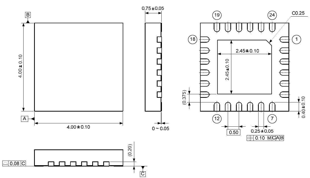
■ Material & Lead Finish Package molding compound: Epoxy Resin Lead frame material: Cu Pin surface treatment: Solder (Pb free) Plate ■ Marking
1 1) 2) 3) 4)
Pin #1 indication Date Code : XXXX (4 digits) Marketing Code : 5522 AKM Logo: AKM 017002311-E-00 2017/03
■ Ordering Guide AK5522VN AKD5522 -40 - 105ºC 24-pin QFN Evaluation Board for the AK5522
Date (Y/M/D) Revision 17/03/28 00 Reason First Edition Page Contents 017002311-E-00 2017/03
information contained in this document without notice. When you consider any use or application of AKM product stipulated in this document (“Product”), please make inquiries the sales office of AKM or authorized distributors as to current status of the Products. 1. All information included in this document are provided only to illustrate the operation and
application examples of AKM Products. AKM neither makes warranties or representations with respect to the accuracy or completeness of the information contained in this document nor grants any license to any intellectual property rights or any other rights of AKM or any third party with respect to the information in this document. You are fully responsible for use of such information contained in this document in your product design or applications. AKM ASSUMES NO LIABILITY FOR ANY LOSSES INCURRED BY YOU OR THIRD PARTIES ARISING FROM THE USE OF SUCH INFORMATION IN YOUR PRODUCT DESIGN OR APPLICATIONS. 2. The Product is neither intended nor warranted for use in equipment or systems that require
extraordinarily high levels of quality and/or reliability and/or a malfunction or failure of which may cause loss of human life, bodily injury, serious property damage or serious public impact, including but not limited to, equipment used in nuclear facilities, equipment used in the aerospace industry, medical equipment, equipment used for automobiles, trains, ships and other transportation, traffic signaling equipment, equipment used to control combustions or explosions, safety devices, elevators and escalators, devices related to electric power, and equipment used in finance-related fields. Do not use Product for the above use unless specifically agreed by AKM in writing. 3. Though AKM works continually to improve the Product’s quality and reliability, you are
responsible for complying with safety standards and for providing adequate designs and safeguards for your hardware, software and systems which minimize risk and avoid situations in which a malfunction or failure of the Product could cause loss of human life, bodily injury or damage to property, including data loss or corruption. 4. Do not use or otherwise make available the Product or related technology or any information
contained in this document for any military purposes, including without limitation, for the design, development, use, stockpiling or manufacturing of nuclear, chemical, or biological weapons or missile technology products (mass destruction weapons). When exporting the Products or related technology or any information contained in this document, you should comply with the applicable export control laws and regulations and follow the procedures required by such laws and regulations. The Products and related technology may not be used for or incorporated into any products or systems whose manufacture, use, or sale is prohibited under any applicable domestic or foreign laws or regulations. 5. Please contact AKM sales representative for details as to environmental matters such as the
RoHS compatibility of the Product. Please use the Product in compliance with all applicable laws and regulations that regulate the inclusion or use of controlled substances, including without limitation, the EU RoHS Directive. AKM assumes no liability for damages or losses occurring as a result of noncompliance with applicable laws and regulations. 6. Resale of the Product with provisions different from the statement and/or technical features set
forth in this document shall immediately void any warranty granted by AKM for the Product and shall not create or extend in any manner whatsoever, any liability of AKM. 7. This document may not be reproduced or duplicated, in any form, in whole or in part, without
prior written consent of AKM.
017002311-E-00 2017/03