⬇ Download Markdown · ⬇ Download LaTeX · ⬇ original · view original · CSV: table 1, table 2
4th International Conference on Sensors, Measurement and Intelligent Materials (ICSMIM 2015)
Yanping Cong 1, a , Haokun Chi 2,b and Zhiqiang Wei 3,c 1,2,3 Ocean University of China, No.238, Songling Road, Laoshan District, Qingdao City, Shandong
Province, China a [email protected], b [email protected], c [email protected] Keywords: Wireless Power Transmission, PCB Rectangular Coil, HFSS, Inductance Abstract. Energy is the material basis of human activities, whether traditional coal, oil, natural gas or wind energy, solar energy, tidal energy and other new energy sources have greatly promoted the development of mankind, but in any case, human beings are inseparable from power. Traditional power can only be transmitted through wires, in 2006 researchers of Massachusetts Institute of Technology[1] first proposed the concept of magnetically coupled resonant wireless energy transfer, and light a 60W bulb using solenoid coils at a distance of 2m. In their power transmission system, reasonable resonator is the key to the system.
In this paper, a printed circuit board (PCB) is used as a resonator of small device. HFSS simulation is applied to verify Youbok Lee’s method[2], inductance formula of any layer particular PCB rectangle coil is further deduced. Then HFSS simulation is applied again to verify inductances of the two and four layers PCB rectangular coil; Finally, the key and secondary factors which can influence inductance of multilayer PCB rectangular coil are located. The conclusion is: for a certain area of PCB rectangular coil, the greater the surface area of the wiring is, the higher the inductance is.
Introduction
Compared to traditional wired power transmission technology, wireless power transmission technology is more convenient, secure, and its use is becoming more and more widespread, it was named one of the ten most promising future research directions. In 2006, the research published by MIT set off a new era in this field.
Domestically, in 2008 Professor Qingxin Yang[3], Tianjin University, analyzed the principle of inductive coupling energy transfer and mathematical model of separation transformer, calculated the coupling coefficient of E-type structure transformer with the change of the transmission distance. In 2009, Professor Yunzhong Zhu[4], Sun Yat-sen University, made a power transmission apparatus using solenoids and capacitors, when the input power is 1W, the diode four meters outside was lighted up, but the transmission efficiency was only 10%. Professor Bo Zhang[5], South China University of Technology, invented a technology which can capture the electromagnetic field using a pair of mutually coupled circuit,which solved the problem of optimal system operating frequency changing with the change of energy transfer distance. In 2010, Professor Sun Yue[6], Chongqing University, studied middle distance wireless transmission. Their transmission indicators were: transmission distance 1.6m, power 60W, efficiency 40%, they also involved in the production of the power part of Haier tailless TV. In 2014, Professor Zhu Chunbo[7], Harbin Institute of Technology, achieved a wireless power transmission system using asymmetric structure coil in the distance of 60 ~ 150mm, and the transmission power is 700W, the transmission efficiency is 80%, the results also showed transmitting and receiving coil which were inconsistent can improve system stability. Professor Weinong Fu[8], the Hong Kong Polytechnic University, using a thin film resonator which resonance frequency was 5.5Mhz, achieved about 50% of the power transfer efficiency at a distance of 20cm. Then they increased the transmission distance by adding repeaters resonator in the middle of transmitting and receiving coils.
Abroad, in 2008, the research group[9] of Intel Corporation in Seattle, lighted a 60W bulb at a distance of 1m using flat spiral coils, and the power transfer efficiency is 75%.In 2010, Fujitsu [10] designed a fast wireless charging technology, which can greatly shorten the charging time of © 2016. The authors - Published by Atlantis Press 184 cellphone. In 2011, Professor John Boys[11], the University of Auckland in New Zealand, designed a charging coil which diameter was 700mm and the output power was 2kW, meeting the charging requirements of electric vehicles. South Korean Science and Technology (KAIST) [12] has developed three generations of OLEV wireless charging system, and promoted the application of wireless power transmission technology.
inductance of planar PCB rectangular coil
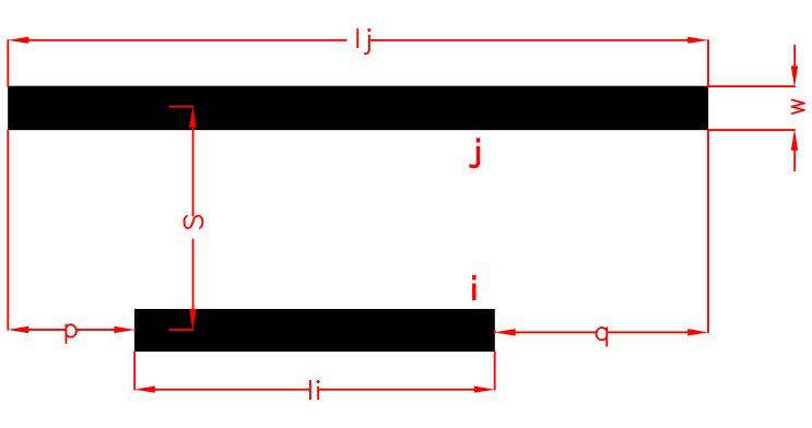
Conveniently, we number each section of the coil in the way of from the inside out, and symbolic significance as follows: indicates the length of section i, w represents the width of copper wiring, s is the distance between the centerlines of adjacent turns (Fig. 2), h_c represents the thickness of wiring (all 0.035mm in this paper), h_f represents the thickness of FR4 substrate (all 0.33mm in this paper), n represents the total number of turns of the coil, lay indicates wiring layers of the coil.
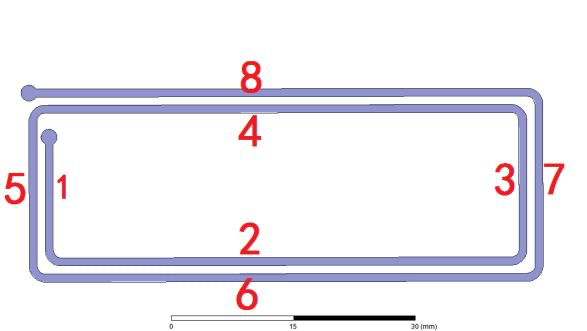
Fig. 1 planar 2-turns rectangular coil and its numbers Fig. 2 coil parameters
inductance calculation of planar rectangular coil The circuit model of n-turns planar coil shown in Fig. 1 is shown in Fig. 3. Because there is mutual inductance, capacitance between each wire and other wire, circuit analysis method is very complex. Therefore, paper[1] proposed a inductance value formula of n-turns planar coil:
4 n 4 n 4 n , j i i 1 i 1 L L i M i , j ( 1 )
j 1 In this formula, Li represents the inductance of section i, Mi.j represents mutual inductance between section i and j, there is M i , j M j , i .
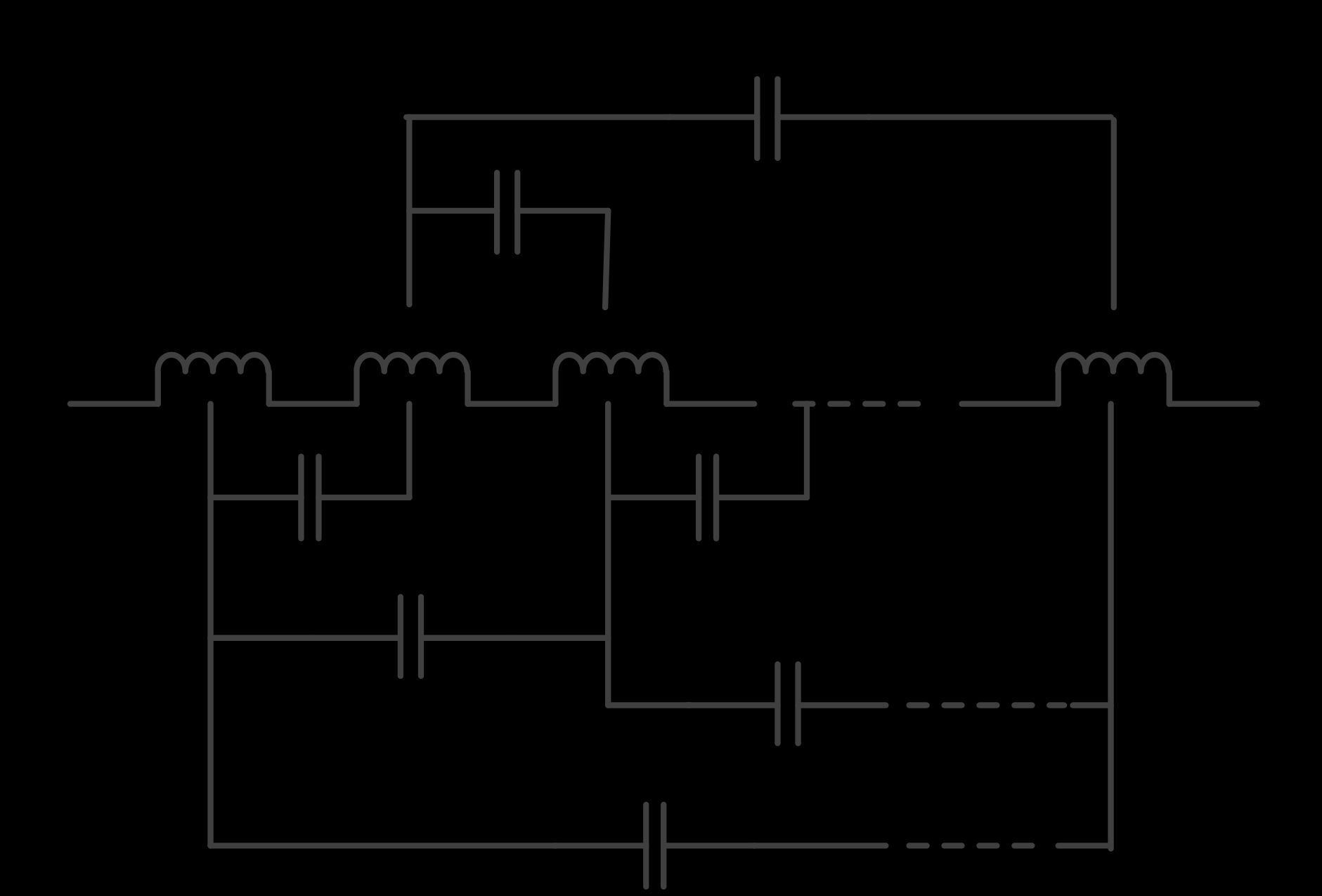
Fig. 3 circuit model of planar PCB coil In order to verify the Eq. 1, we designed five single-layer PCB rectangular coils(copper wire), detailed parameters are list in Table 1, inductances of theoretical calculations and HFSS simulation results are compared, the results are as Fig. 4. It can be seen that the theoretical results and simulation results are very similar. In addition, by comparing the number 1, 2 coils, It can be found that increasing the line width will reduce inductance, but the impact is not great; By comparing 3,4 coils, it can be seen that increasing the distance between the centerlines of adjacent turns can also cause inductance reducing, and the impact is relatively large; By comparing the numbers 3,5 coil, turns can be seen to be positively correlated with the inductance, and the impact is great, too.
185 wiring layers number coil parameters turns n linewidth w(mil)
The first layer 8 The first layer 8 The first layer 15 The first layer 15 The first layer 30 Table 1 parameters of coil 1-5 1 2 3 4 5 20 40 10 10 10 the distance between the centerlines of adjacent turns s(mil)
80 80 20 40 20 30
Simulation results theoretical results 25 L(uH)
20 15 10 5 1 2 3
number 4 5
Fig. 4 simulation and theoretical inductances of coil 1-5 inductance of 3-D PCB rectangular coil
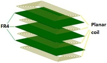
Fig. 5 the structure of four-layer PCB coil
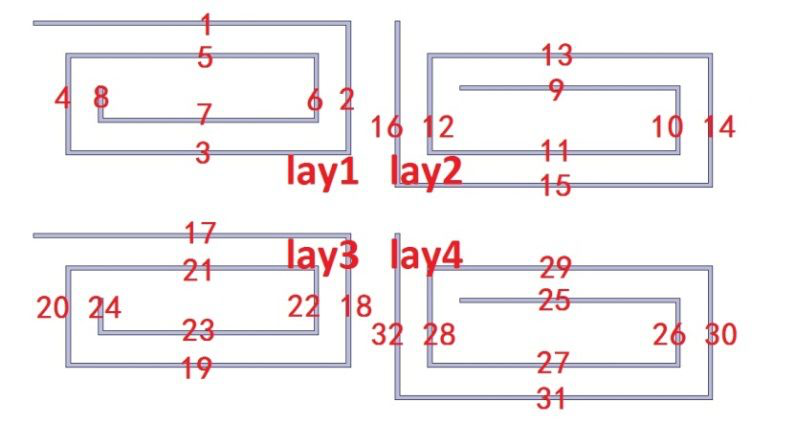
Fig. 6 number of four-layer two-turns coil 186
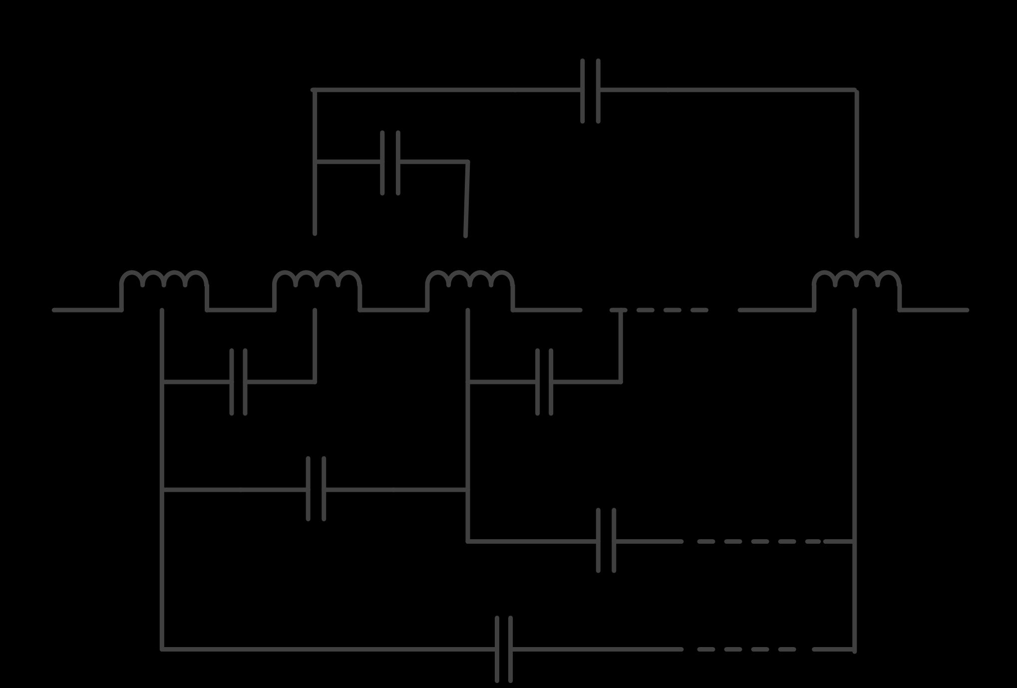
Fig. 7 circuit model of four-layer two-turns coil The structure of 3-D PCB coil is shown in Fig. 4, the material of is FR4 epoxy glass fiber, and there are rectangular planar coils on both sides of each substrate, its circuit model is shown as Fig. 6. Each layer is connected with the next layer in the form of end to end, and the structure of the odd layers and even layers are respectively same. We number each section from small to large according to current flow starting from the first layer, and a four-layers two-turns coil’s number is as shown in Fig. 5. Thus, the current direction of the straight wires which number’s difference is a multiple of 4 is the same. The formula of its inductance is as followed:
32 32 32, j i i 1 i 1 L total L i M i , j (2)
j 1 In this formula, Li denotes inductance of a straight wire of section i, according to empirical formula of Калантаров[13], there is:
2 l i w h _ c ( 3 ) L i 0.002 l i {ln( ) 0.50049 } w h _ c 3 l
iM i.j represents the mutual inductance between two straight wires i and j. When the current direction of the two straight lines is perpendicular to each other, M i.j can be ignored, denoted by 0; When the current direction of the two straight lines is same, M i.j plays a positive role in the total inductance; When the current direction of the two straight lines is reversed,M i.j plays a negative role in the total inductance. And there is:
0 if i j 2 k 1, k Z _ (4) M i , j M i , j if i j 4 k , k Z
_ M i , j else _ _ M i , j represents the absolute value of M i , j , the M i , j between two straight wires shown in Fig. 2 is solved by[1]:
_ 1 M i , j (( M i p M i q ) ( M p M q ))
2 ( 5 )
_ d d l l M K 2 l k {ln[( k ) 1 ( k ) 2 ] 1 ( k , j ) 2 k , j } d
k , j d k , j l k l k (6) d k,j is the distance between lines k and j, which can be obtained from distance of the vertical direction (associated with h_f and h_c),distance of the horizontal direction (related with s and l k+1 ) and the Pythagorean theorem.Eq. 2 is extended to three-dimensional rectangular n-turn PCB coil, the inductance formula is:
187 4 n 4 n 4 n , j i i 1 i 1 L L i M i , j (7)
j 1 In order to verify Eq. 7, we designed a total of six coils (No. 6-11) which parameters is show in Table (2), simulation and theoretical results are shown in Fig. 8. As can be seen, the relative error between theoretical and simulation results becomes larger with the increasing of the number of layers; By comparing the numbers 6,7,8 coils, it can be seen, when the wiring layer is two layers, coil inductance increased with the decreasing of the distance between the layers; By comparing the numbers 9,10 coils it can be found that increasing the distance between the centerlines of adjacent turns will reduce the inductance; 10,11 coils show that increasing the width of the coil decreases inductance. This is consistent with the previous results.
the distance between the turns linewidth centerlines number wiring layers n w(mil)
of adjacent turns s(mil) 6 the first and 8 40 120
second layers 7 the first and 8 40 120 third layers coil 8 the first and 8 40 120 parameters
| 9 | all four layers 32 | 10 | 70 |
|---|---|---|---|
| 10 | all four layers 32 | 10 | 80 |
| 11 | all four layers 32 | 15 | 80 |
| Table 2 parameters of coil 6-11 | |||
| 7 | 40 |
Simulation results theoretical results 6 39
38
37 L(uH) L(uH)
5 4 36
35
34 3
33
2
6 7
number 32 8 9 10
number 11 Fig. 8 simulation and theoretical inductances of coil 6-11 Summary
In this paper, finite element inductance calculation algorithm in the article[2] is generalized, inductance formula of multilayer PCB rectangular coil (total number of turns is n) is derived, the theoretical and simulation inductance of 11 PCB coils are compared. By analyzing the influencing factor of PCB rectangular coil inductance, conclusions are as follows: Linewidth has less impact on the inductance, and it is a secondary factor; The distance between the centerlines of adjacent turns and turns, as the main factors, have greater impact on the inductance. The turn of coil has a positive correlation with the inductance; Linewidth, the distance between the layers, the distance between the centerlines of adjacent turns have a negative correlation with the inductance. That is to say, the greater the surface area of the wiring is, the higher the inductance is.
188 Acknowledgements This paper received funding of China International Scientific and Technological Cooperation Special (2013DFA10490) and Qingdao innovation and entrepreneurship leading talent project(13-cx-2).
References [1] Soljacic M. Wireless non-radiative energy transfer. presentation archived at the website of
American Institute of Physics, http://www.aip.org/ca/2006/soljacic.pdf. [2] S.C.Tang, S.Y.Hui, and H.S.-H.Chung, Characterization of coreless printed circuit board
(PCB)\ntransformers, IEEE Trans. Power Electron., vol. 15, no. 6, pp. 746–752, 2000. [3] Junhua Wang,Jiangui Li,Youhua Wang,Qingxin Yang. Research applied to non-contact power
transmission system separable transformer [J]. transformer,2008,45(8): 26-29. [4] Yunzhong Zhu,Ling Pu, Haiqiang Zeng. a small power-efficient wireless energy transmission
system drived by the switching circuit. SEN UNIVERSITY(Natural sciences).2009,7 [5] Wenzhen Fu,Bo Zhang,Dongyuan Qiu. Research of frequency tracking resonant coupling
wireless power transmission system.Beijing. 2009,4 [6] Chenyang Xia. Analysis and optimization of inductively coupled power transfer system efficiency
characteristics[D]. Chongqing University. 2010. [7] Chunlai Yu, Rengui Lu, Yinhua Mao, Litao Ren, Chunbo Zhu. Research on the Model of
Magnetic-Resonance Based Wireless Energy Transfer System[C]. Vehicle Power and Propulsion Conference, 2009. VPPC '09. IEEE. Dearborn, MI. 2009, Sept: 414—418. [8] F. Zhang,S. A. Hackworth,W. N. Fu. Relay Effect of Wireless Power Transfer Using Strongly
Coupled Magnetic Resonances, IEEE Transactions on magnetics,2011,47:1478-1481. [9] CCND2014. The second generation of wireless charging technology is expected to become
mainstream[N]. People's Post. 2014-06-26 [10] Zhang Xian, Yang Qingxin, Chen Haiyan, Li Yang, Yan Zhuo. The application of non-contact
power transmission technology (NPT)in the modern transport system[C]. Mechatronics and Automation(ICMA), 2010 International Conference on, 2010,2010:345-349. [11] Grant A. Covic, Michael L. G. Kissin, Dariusz Kacprzak, Niels Clausen, and Hao Hao. A
Bipolar Primary Pad Topology for EV Stationary Chaiging and Highway Power by Inductive Coupling[C]. Energy Conversion Congress and Exposition (ECCE), 2011 IEEE. Phoenix, AZ. 2011 [12] Jin Huh, Wooyoung Lee, Gyu-Hyeong Cho, Byunghun Lee, Chun-Taek Rim. Characterization
of Novel Inductive Power Transfer Systems for On-Line Electric Vehicles[C]. Applied Power Electronics Conference and Exposition (APEC),2011 Twenty-Sixth Annual IEEE. Fort Worth, TX. 2011, March: 1975-1979. [13] Kаnантаров, Manual of Inductance Calculation [M]. Beijing: Mechanical Engineering Press,
1986 189