
⬇ Download Markdown · ⬇ Download LaTeX · ⬇ original · view original
1
Matt Landreman 1 , Siena Hurwitz 1 , and Thomas M Antonsen, Jr. 1
1 Institute for Research in Electronics and Applied Physics, University of Maryland, College Park, MD 21043 USA For designing high-field electromagnets, the Lorentz force on coils must be computed to ensure a support structure is feasible, and the inductance should be computed to evaluate the stored energy. Also, the magnetic field and its variation inside the conductor is of interest for computing stress and strain, and due to superconducting quench limits. For these force, inductance, energy, and internal field calculations, the coils cannot be naively approximated as infinitesimally thin filaments due to divergences when the source and evaluation points coincide, so more computationally demanding calculations are usually required, resolving the finite cross-section of the conductors. Here, we present a new alternative method that enables the internal magnetic field vector, self-force, and self-inductance to be computed rapidly and accurately within a 1D filament model. The method is applicable to coils for which the curve center-line can have general noncircular shape, as long as the conductor width is small compared to the radius of curvature. This paper extends a previous calculation for circular-cross-section conductors [Hurwitz et al, arXiv:2310.09313 (2023)] to consider the case of rectangular cross-section. The reduced model is derived by rigorous analysis of the singularity, regularizing the filament integrals such that they match the true high-dimensional integrals at high coil aspect ratio. The new filament model exactly recovers analytic results for a circular coil, and is shown to accurately reproduce full finite-cross-section calculations for a non-planar coil of a stellarator magnetic fusion device. Due to the efficiency of the model here, it is well suited for use inside design optimization.
Index Terms—Electromagnetic coil, self-inductance, magnetic energy, self-force, Lorentz force, stellarator, nuclear fusion, critical current
I N a configuration of electromagnets, important quantities include the Lorentz forces, inductances, and magnetic fields inside the conductors. The forces determine the necessary support structure, and the inductances determine the stored magnetic energy and dynamics. The magnetic field in the conductor determines local forces and their shear, and in superconductors the field also determines the critical current. For general steady currents, the field is determined via a threedimensional (3D) Biot-Savart integral,
where J is the current density. Similarly, the force per unit length dF/dℓ is determined by a 5D integral, given by integrating (1) over the conductor’s cross-sectional area, and the self-inductance L is given by a 6D integral:
where I is the current, and the stored energy is W = (1/2)LI 2 . If one considers two thin coils A and B that are separated by more than the conductor width, the effect of one on the other can be computed by approximating them as infinitesimally thin filaments. The field and force at a point r A reduce to 1D integrals over coil B,
Corresponding author: M. Landreman (email: [email protected]).
where t is the unit tangent vector. Similarly, the mutual inductance M can be computed with a 2D integral over both
This reduction in dimensionality is extremely advantageous for simplicity and speed of computation. The self-field, selfforce, and self-inductance of a coil cannot be computed by setting B → A in (3)-(5) due to the singularity in the denominators when the source and evaluation points coincide. However, in this paper we will derive modified singularityfree 1D integrals for efficient calculation of the self-field and self-force, and a 2D integral for calculation of the selfinductance. The new formulas here are derived by rigorous analysis of the region where source and evaluation points nearly coincide, resolving the singularities in the filamentary integrals appropriately to have the correct asymptotic behavior. For one example documented in this paper, calculating the selfforce per unit length using the reduced model derived here is ∼ 18,000 times faster than using the original high-dimensional integral.
One motivating application for our work is the design of electromagnets for magnetic confinement fusion. These magnets have a large bore to enclose the plasma that they confine. Confinement of the plasma improves with field strength [1], so high fields are employed, and supporting the large Lorentz forces is a serious concern [2]. The reduction of the critical current for superconductivity due to the large field is also important. Figure 1 shows an illustrative example of a fusionrelevant magnet, one of the non-planar coils for the Helically Symmetric eXperiment (HSX) at the University of Wisconsin [3]. The shapes of fusion magnets, particularly for the stellarator concept, may be designed by optimization. It is therefore 2
term is negligible in most of the integration domain, but it becomes significant when the distance between source and evaluation points is small, comparable to the coil thickness. Physically, this term reflects the fact that when the source and evaluation points are this close, the finite thickness of the conductor cannot be neglected in the true high-dimensional integrals. In the reduced integrals, a factor of order unity is present multiplying the regularization term, and it is calculated rigorously to match the behavior of the true high-dimensional integrals.
This paper builds on our previous work in [8] for thin coils with circular cross-section. In the present work, similar techniques are applied to coils where the cross-section is rectangular. The case of rectangular cross-section is more complicated because the orientation of the cross-section must be specified, affecting some aspects of the calculations. Many details of the calculation here differ from and are more complicated than the circular-cross-section case, although the final results have similarities in form.
One important assumption in our method is that the current density is uniform across the conductor cross-section. At a coarse-grained level, this model of the current distribution is accurate for a coil composed of multiple turns in both the transverse directions, as each turn carries the same current. This model may not be highly accurate for high temperature superconducting (HTS) tapes, in which case the current may distribute itself non-uniformly in the transverse dimension along the tape [15], [16]. The uniform-current-density model also does not account for skin currents associated with diamagnetism that may be relevant for some superconductors. Nonetheless, the model here may still be useful for superconducting coils for initial estimations or use inside design optimization. A uniform current density approximation has been used for superconducting coils by other authors coils, e.g. section 2.2 of [17].
In the following section, the problem geometry is defined and coordinates are established. Then in section III, the main results are collected together for convenience. The methodology for deriving these results is explained in more depth in section IV. Sections V-VII give specific details of the selfinductance, self-field, and self-force calculations respectively. The reduced integrals have fine-scale structure in the integrand, and in section VIII we show how to remove this structure analytically so the integrals can be evaluated accurately on coarse grids. Finally the results are discussed in section IX, where we conclude.
The conductor is considered to have a rectangular crosssection with side dimensions a and b at all points along its length. We define coordinates to parameterize the conductor volume. A periodic angle-like coordinate ϕ ∈ [0, 2π) will be used parallel to the conductor, while coordinates u, v ∈ [−1, 1] will be used in the transverse directions. The position vector r is expressed as
gray.
where r c (ϕ) is the position vector of the coil center-line, and p, q are unit vectors in the perpendicular plane aligned with the conductor cross-section. These definitions are illustrated in figure 3. The goal of our approach will be to express the inductance, self-force, and field strength in terms of integrals over ϕ involving r c .
The unit tangent of the center-line is t = |r ′ c | −1 r ′ c , where primes denote d/dϕ. The set {t, p, q} forms an orthonormal curve frame for r c . We consider this frame to be right-handed:
finds [18]
vature κ(ϕ) of the center-line is the magnitude
pof the derivative of t with respect to arclength, hence κ = κ 21 + κ 22 . Noting the top row of (7) is also equal to κn|r ′ c |, where n is the unit normal, then κ 1 p + κ 2 q = κn. Crossing with t gives
where b = t × n is the binormal. To compute κ 1 and κ 2 , one
that since the {t, p, q} curve frame is defined to align with the rectangular conductor cross-section, the frame is smooth at any points or segments where κ = 0, in contrast to the Frenet frame.
From (6)-(7), the Jacobian of the (ϕ, u, v) coordinates is
We consider the current density to be
where I is the total current, i.e. uniform in magnitude throughout the conductor. Using the formula for the divergence in curvilinear coordinate systems, it can be verified that (10)
4 where
Fig. 4. The dimensionless quantities k and δ defined in (12)-(13) appearing in the reduced models.
For convenience, our main results are collected in this section. These expressions are derived in later sections of the paper. The self-inductance L is given by
These last two quantities are plotted as a function of the aspect ratio b/a in figure 4. For a cross-section that is square, k =
δ = a/(be 3 ). As usual, the stored energy follows immediately from W = (1/2)LI 2 . For simplicity, the number of turns N is taken to be one; in the multi-turn case, one merely needs to multiply the inductance expressions throughout this paper by N 2 .
The self-force per unit length is
where
In (17), (19), and throughout this paper, the sums are over s u = ±1 and s v = ±1. The term B 0 is the field of an infinite straight wire with the same rectangular cross-section as our original general coil.
In the formula (16) for B, observe that B 0 ∼ µ 0 I/a, whereas B κ and B b are much smaller: ∼ µ 0 Iκ. Thus, for most applications, B κ and B b can be neglected. We nonetheless retain them here because for computing the cross-sectionaveraged Lorentz force, B 0 gives a vanishing contribution to leading order, so these higher order terms are required.
As anticipated in the introduction, the reduced integrals (11) and (15) have a regularizing term in the denominator, δab. Without this term, which prevents division by zero, the integrals would reduce to the expected integrals for infinitesmally thin coils. This new term is negligible compared to the adjacent term |r c − r̃ c | 2 in most of the integration region. However, where the separation between the source and evaluation points r̃ c and r c is comparable to the dimensions of the cross-section, the regularizing term δab becomes important.
Note that the inductance (11) and force (14) are independent of the angle by which the cross-section is oriented.
Finally, we will show that equivalent formulas for computing (11) and (15) which can be more accurate numerically are
and
5
In both (22) and (23), the last term cancels the near-singularity in (11) and (15), so the integrands are significantly smoother. Therefore the integrals can be evaluated to reasonable accuracy with many fewer quadrature points.
We now proceed to show how the formulas of this section are derived.
To rigorously justify the reduced formulas (11)-(21), we begin by establishing orderings. Let R indicate the large spatial
small parameter a/R ≪ 1. Moreover, an intermediate scale d is introduced, satisfying
where A is the vector potential satisfying B = ∇ × A. Thus,
Tildes indicate quantities evaluated at the source location specified by the integration variables. As explained in the previous section, the total potential is written as a sum of near and far contributions, partitioned in ϕ. Using (10),
(27)
(28)
Based on this decomposition, (25) gives the self-inductance as a sum of the two corresponding terms:
(24)
Associated with d, we define an angle ϕ 0 = d/R. In the original high-dimensional integrals for the inductance and field, we separate the integrals into a sum of two parts, depending on whether the source and evaluation ϕ locations are within ϕ 0 or not. This condition reflects whether the source and evaluation points are within a distance d or not. In the “far” term, where the difference in ϕ exceeds ϕ 0 , the finite cross-section of the conductor can be neglected, resulting in a substantial simplification of the integrals. In the “near” term, where the source and evaluation ϕ values are within ϕ 0 , the shape of the coil can be Taylor-expanded. The resulting simplified integrals can then be performed analytically. Now that the total quantity (inductance or field) has been expressed as a sum of two simplified terms, a reduced 1- or 2-dimensional integral is proposed as an ansatz. The proposed integral is similarly written as a sum of near and far contributions. The near parts of the high-fidelity and reduced models are shown to be equal. Similarly, the far parts of the high-fidelity and reduced models are equal. Thus, the high-fidelity and reduced models are equivalent in the limit a/R ≪ 1.
A related method of introducing an intermediate scale has been used previously for inductance problems. See e.g. page 123 of [19], or [14].
We now proceed to apply this procedure to the inductance, force, and field in the following sections. The force can be computed either directly, by integrating the force density J × B, or indirectly by applying the principle of virtual work to the inductance. The latter turns out to be convenient because it requires only lowest-order terms, whereas the direct calculation of the force requires finding higher-order terms in the field.
(26)
In these last two lines, note that the ϕ integrals without tildes still cover the full interval [0, 2π).
For the far contribution, |r − r̃| ≫ d, so all of the nonzerothickness terms can be dropped: r − r̃ ≈ r c − r ˜ c . Also the Jacobian (9) can be approximated as
To evaluate A near and L near , quantities in (27) are Taylorexpanded about ϕ ′ ≈ ϕ. Details of the evaluation of A near and L near are given in appendix A. After a lengthy calculation, the result is
with k given by (13).
We now propose an ansatz of the form (11), where δ remains to be determined. Calling this expression L f il , we can write it without approximation as a similar sum of two terms:
(36)
(37)
6 Julia implementation of the algorithm in [21]. Code used for all the numerical computations in this paper can be obtained at [22] and [23].
Figure 5 shows a comparison of the reduced model (11) with the high-fidelity 6D integral (2) for the HSX coil. To test the dependence on a and b in (12)-(13), the aspect ratio of the cross-section b/a is varied from 0.1 to 10 for three values of a. For comparison, the length of the coil is l = 2.05 m, comparable to a circle with radius l/(2π) = 0.327 m. The figure shows that the reduced model agrees extremely well with the high-fidelity model. Differences are imperceptible on the scale of the plot except at the largest values of a and b, where the expansion is not as accurate.
If the coil consists of N turns, with current I N = I/N per turn, the current density and hence magnetic energy W is unchanged. The inductance L N in this case is defined by W =
In the case of a circular coil, the inductance expressions here for both the high-fidelity and reduced models simplify to a classical formula. This result is shown in appendix D.
Fig. 5. The self-inductance of the HSX coil in figure 1, computed with the 2D reduced model (11) (dashed curves), closely agrees with highfidelity calculations using the 6D integral (2) (solid curves). The agreement is excellent across a wide range of values for the conductor cross-section dimensions a and b.
In the far term, the δab term in the denominator is negligible
result
if we choose δ according to (12). Thus, the high-fidelity calculation of L by (25) rigorously agrees with (11) in the
We can now confirm the accuracy of the reduced model (11) by numerical comparison to the high-fidelity 6D integral (2). Throughout the paper, such comparisons between high-fidelity and reduced models will be made using the HSX coil displayed in figure 1. The rectangular cross-section is chosen to be oriented along the “coil centroid frame” described in [20].
RThis frame is defined in terms of the centroid C = (1/l) dℓ
Rr c , where dℓ = |r ′ c |dϕ is the incremental arclength and l = dℓ is the total length. The frame is defined by
where w = r c − C. Thus, p is a vector pointing outward from the centroid, projected to be orthogonal to the tangent. Here, and in later sections of the paper, the multi-dimensional integrals are evaluated using the HCubature.jl package, a
Now we derive the model for the magnetic field inside the conductor, (16)-(21). As explained in section IV, we will proceed by showing that the near and far parts of the high fidelity model match those of the reduced model. There are two options for computing B: either compute A to the requisite order and then take the curl, or directly evaluate the Biot-Savart law (1). Here we will follow the latter approach. (To find B to the desired accuracy from A, A would need to be computed to higher order than the calculation in Appendix A.)
Similar to section (V), we begin by writing the highfidelity expression (1) as a sum of near and far contributions,
In the far term, the source and evaluation points are at least a distance ∼ d ≫ a apart, so the thickness of the conductor can be neglected. Hence we can approximate r ≈ r c and use (32), with the result
To evaluate B near , quantities in (42) are Taylor-expanded about ϕ̃ ≈ ϕ. Details are relegated to Appendix B. The result obtained is
7
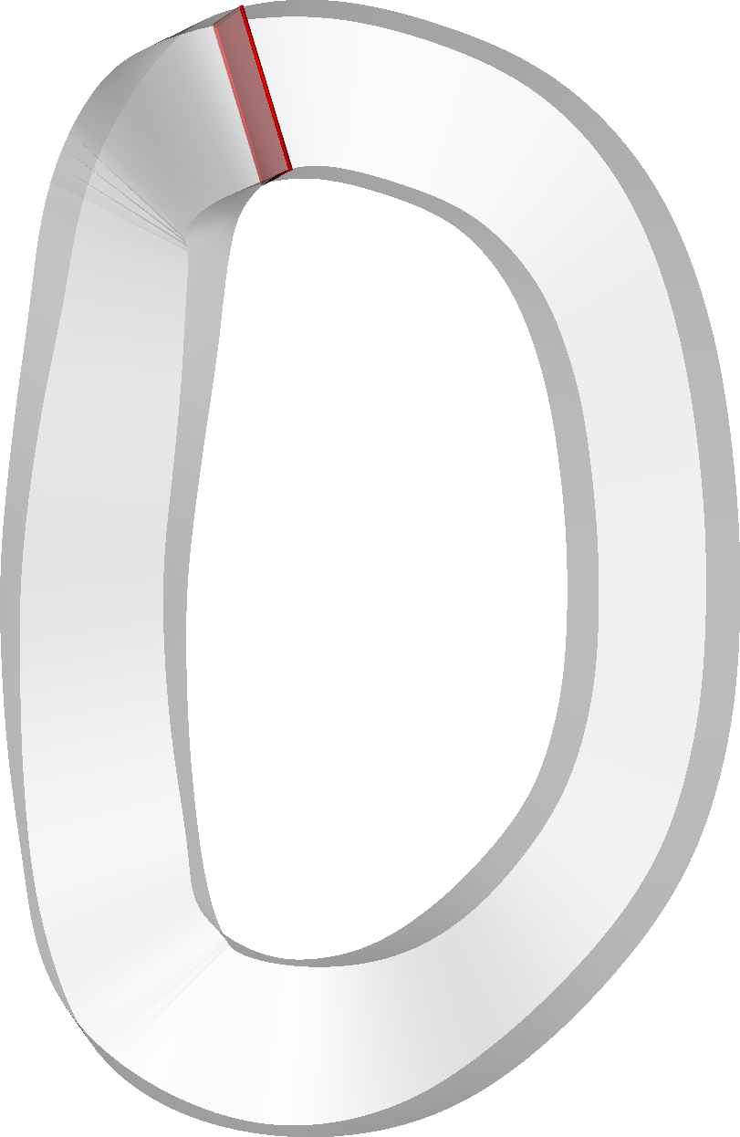
Fig. 6. Magnetic field inside the conductor of the HSX coil, for the cross-section highlighted in red at left. The reduced model (16), requiring only a 1D integral, agrees well with the high fidelity model - the 3D integral (1). Both the field magnitude and one component (z) are shown.
where B 0 is the field of an infinite straight wire in (17), and
Now that the far and near behavior of the high-fidelity model is determined, we can guess a form for a reduced model with only a 1D integral. In contrast to the inductance and force, the near internal field depends on u and v, which would not be captured by a 1D integral alone like (11) or (14). Therefore we must add this local variation. A natural ansatz is
for some B uv (ϕ, u, v) to be determined, where B reg is given
approximate r c − r̃ c ≈ (ϕ − ϕ̃)r ′ c in the denominator, and use
The reduced model derived here is demonstrated in figure
coil. In the the left panel of figure 6, the cross-section is shown as a red rectangle. The field magnitude and one field component are displayed in the right four panels, both for the reduced model (16), and for the original 3D Biot-Savart integral (1). The current is taken to be 150 kA. The highfidelity and reduced models agree well. For coils in which the cross-section dimensions are smaller relative to the coil curvature, the agreement improves further.
The self-force can be computed from the self-inductance using the principle of virtual work, as explained in section 3 of [13]. A perturbation ∆r to the curve shape is considered, with the current varying to keep the flux Φ = LI fixed so there is no induced voltage. The change to the energy W = (1/2)LI 2
the result
This same result can also be derived by considering the shape perturbation ∆r c to be at fixed current. In this case, in addition to the mechanical work, the energy varies also due to the time integral of the IV power associated with the voltage V = dΦ/dt since the flux varies.
Thus, we consider a perturbation to r c in the inductance formula (11): r c → r c + ∆r c . For the terms in which the perturbation acts on the tilde position vector, we can swap the tilde and non-tilde variables. Integrating by parts to collect factors of ∆r c , we obtain
Equation (52) with (53) must hold for any perturbation ∆r c (ℓ), implying the integrands are equal. Thus, the force formula (14) with (15) follows.
8 We can also show the same result (14) can be obtained by integrating the Lorentz force density over the conductor crosssection. In this approach we proceed as discussed in section IV: the high fidelity calculation is divided into near and far regions, and the reduced model (14) with (15) is shown to give the same near and far contributions.
RBeginning with the volume-integrated Lorentz force F = d 3 rJ × B, applying
force per unit length:
Taking advantage of our earlier decomposition (41)-(43), we have
where
Fig. 7. The self-force of the HSX coil, computed with the 1D reduced model (14) (dashed curves), closely agrees with high-fidelity calculations using the 5D integral (54) (solid curves). The z component of the force per unit length is displayed, averaging over the red cross-section shown in figure 6. The agreement is excellent across a wide range of values for the conductor crosssection dimensions a and b.
The integral (56) is done in appendix C, with the result
where k is again given by (13). Next, we consider an ansatz for the force of the form (14) with (15), but not assuming any particular value for δ. Dividing up the range of the ϕ integral as usual, the 1D filament model for the force per unit length is
where
choose δ in (15) according to (12). Thus, the near part of the high-fidelity model equals the near part of the reduced model, and the far part of the high-fidelity model equals the far part of the reduced model. As discussed in appendix C, this direct approach to justifying the reduced model required high-order terms in B near , whereas the virtual work approach required only the leading-order vector potential via the inductance.
The reduced 1D expression for the force agrees quantitatively with the high fidelity 5D integral (54) in numerical calculations. One demonstration of this agreement is shown Fig. 8. Another demonstration that the self-force of the HSX coil, computed with the 1D reduced model (14) (dashed curve), closely agrees with highfidelity calculations using the 5D integral (54) (solid curve). Here the true cross-section dimensions of the HSX coil are used. The z component of the force per unit length is displayed, averaging over the cross-section. The agreement is excellent at all points along the coil.
in figure 7. Here, the two models are evaluated for the HSX coil at the red cross-section highlighted in figure 6. Again, the current is taken to be 150 kA. A particular component (z) of the self-force is plotted in figure 7 for a range of crosssection dimensions a and b. Differences between the highfidelity and reduced models are imperceptible on the scale of 9
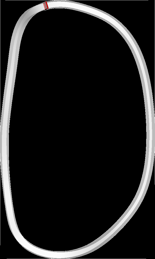
Fig. 9. Integrand for B reg without and with the singularity subtraction method of section VIII. The coil geometry is shown in the 3D inset, with the red cross-section indicating where B reg is being evaluated. Singularity subtraction removes the fine structure from the integrand, easing the resolution required for accurate integration.
Fig. 10. Convergence of the self-force (14) at one point along the coil (ϕ = 0) with respect to the number of quadrature points, without and with the singularity subtraction method of section VIII. With singularity subtraction, comparable accuracy can be obtained with many fewer quadrature points.
ϕ, the integrand in (11) is the plot except for the thickest cross-section, for which the a ≪ R expansion is less accurate.
A second demonstration of the accuracy of the reduced model is presented in figure 8. Here, the cross-section dimensions from figure (1) are used: a = 13 cm and b = 6 cm, matching the real HSX experiment. In figure 8, a component of the self-force is plotted at all points along the coil, computed using both the high-fidelity and reduced models. Even for this thick conductor, the agreement is excellent.
Here we explain the derivation of (22) and (23). Although in sections IV-VII we have reduced the integrals to two or one dimension, the integrals (11) and (15) still require high resolution in the remaining dimension(s) due to fine structure in the integrands in the nearly singular region. This structure can be seen in figure 9. Here, the integrand for one component of B reg is plotted for the HSX coil at the point highlighted in figure 6. The dimensions a and b are reduced to 2 cm since the issue becomes more pronounced for thin cross-sections. The fine structure in the integrand is apparent near ϕ̃ = 0. Further computational efficiency can therefore be gained by manipulating the reduced integrals (11) and (15) to remove the fine-scale structure. We proceed by expanding the integrands of (11) and (15) about the nearly singular point. A term with the same behavior which can be integrated analytically is then subtracted and added. This calculation is similar to the one in [8].
Beginning with the inductance, and expanding r̃ c about ϕ̃ ≈
To make the quantity on the right periodic, we replace
(61)
(62)
since the right and left expressions are the same to second order near ϕ̃ ≈ ϕ. When the result is subtracted and added to (11), one of the terms is integrated analytically using
where K is the complete elliptic integral, and ∆ =
Next, we proceed in a similar way for B reg . Expanding r̃ c about ϕ̃ ≈ ϕ, the integrand in (15) is
Again, (62) is applied to make the quantity on the right of (64) periodic. When the result is subtracted and added to (15), one of the terms is integrated analytically using
for ∆ ≪ 1, where E and K are complete elliptic integrals.
10 The blue curve in figure 9 shows how this singularitysubtraction method removes the fine-scale structure from the integrand for B reg . We therefore expect the number of quadrature points required for accurate integration to be substantially reduced. This expectation is borne out in figure 10, which shows the convergence of the self-force with respect to the number of quadrature points. The coil parameters are the same as in figure 9, and uniformly spaced quadrature points in ϕ̃ with uniform weights are used. It is clear that the singularitysubtraction method greatly improves the convergence. Similar behavior is observed for the inductance (not shown).
For a comparison of the computational savings that can be gained by the reduced models in this paper, we have computed the self-force per unit length for the point along the coil in figure 6, both by integrating over the full finite-thickness cross-section (eq (54) and using our reduced 1D model (eq (14)-(15)). Adaptive quadrature is used for the 5D integral, while uniformly spaced quadrature points are used for the 1D integral. Both formulas are evaluated in Julia on one core of a 2020 M1 Macbook laptop. For three significant digits in the result, the high fidelity calculation takes 1.0 s, whereas the reduced model takes 57 µs, a factor of ∼ 18,000 speed-up.
In this work we have derived reduced expressions for efficiently calculating several quantities of interest for electromagnets: the self-inductance, magnetic energy, field inside the conductor, and self-force per unit length. These quantities normally must be computed by numerical calculations that resolve the cross-section of the conductor, involving high-dimensional integrals or equivalent partial differential equations. Here, by using analytic methods to reduce the problem, the quantities can be computed using only 1D integrals (for the self-field and self-force) or 2D integrals (for the self-inductance and energy). The main results have been collected in section III. The reduced models were formulated to rigorously match the original high-fidelity formulas in the limit that the conductor cross-section dimensions were small compared to the curvature of the coil center-line. Interestingly, the inductance, energy, and force-per-unit-length are found to be independent of the angle by which the rectangular cross-section is oriented. Throughout the paper, the reduced models have been compared to high-fidelity calculations in which the conductor crosssection is fully resolved. The agreement is excellent even for complicated coil shapes such as that in figure 1.
A key assumption of this work was that the current density was uniform across the cross-section. This approximation is accurate if there are many turns of the conductor in both dimensions of the cross-section. However the uniform-currentdensity approximation might not be sufficiently accurate in superconducting coils for some quantities of interest. For example, the distribution of current across a high-temperaturesuperconducting tape is typically nonuniform [15], [16], determined by physics not included here. The critical current of a superconducting coil is a property of practical importance, and precise computation of the critical current likely requires determination of this nonuniform current distribution by a method as in [17]. However, the internal field computed by (16) might at least provide an estimate for the critical current, as follows. First the coil current I is initialized to a plausible value; I will be updated later. Given B from (16), a formula for the local critical current density j c in terms of the local field (such as eq (6) of [16]) gives the local critical current density. This current density could be integrated over the cross-section to get a critical current at each ϕ, and minimization over ϕ would then give an estimate for the overall critical current I c :
Root-finding in one variable could then be applied to solve for the coil current I such that I c = I, consistent with (66). This approach corresponds to the first iteration of the self-consistent numerical solution in [15], [16].
One other limitation of the work here is that sharp corners in the coil center-line are disallowed. It might be possible to address this case in future research.
In this work, the force per unit length was computed by averaging the Lorentz force over the cross-section. However other quantities related to Lorentz forces may also be of interest, including local force variation within the conductor crosssection, and stresses associated with gradients of the local force density. These additional quantities can be computed also using the approach here, since the full magnetic field vector within the conductor has been derived, (16).
A potential application for the results of this paper is in design optimization of electromagnets. One might wish to optimize the shapes of magnets for reduced peak forces, reduced magnetic energy, or reduced peak field. In optimization, it is necessary to evaluate the objective function many times, so speed of evaluation is a priority. Therefore the efficient formulas here will be advantageous.
A PPENDIX A D ETAILS OF THE NEAR VECTOR POTENTIAL AND
SELF - INDUCTANCE CALCULATION Now we evaluate A near . Again (32) can be used. In (27), r̃ ′ c and t̃ can be approximated by the corresponding quantities at the non-tilde (evaluation) point. In the denominator, for most of the integration domain, ϕ − ϕ̃ ∼ ϕ 0 = d/R, in which case |r − r̃| ≈ ϕ − ϕ̃ |r ′ c |. However if this expression is used in (27), the integral diverges near ϕ ≈ ϕ 0 . Evidently, more care is required in an inner layer where ϕ − ϕ̃ ∼ a/R. In this layer, we have to leading order
This expression is valid also in the rest of the near integration region where ϕ − ϕ̃ ∼ ϕ 0 . Thus,
11 The ϕ̃ integral is done using
where (8) has been used. The terms on the right-hand side have a relative ratio of d 2 /(aR) which is not obviously large or small. Using (32) and |r̃ ′ c | ≈ |r ′ c | for the Jacobian, we have
12
We thus find the complete magnetic field through order µ 0 I/R is
where the new term is
Evaluating the ũ and ṽ integrals, and forming the sum (84) with (81), we arrive at (45).
A PPENDIX C D ETAILS OF THE NEAR SELF - FORCE CALCULATION In this appendix some details of the derivation of (58) are presented. The starting point is (56) with (45). Note that in B near in (45), the largest term is B 0 ∼ µ 0 I/a, whereas the other terms are ∼ µ 0 I/R. If the quantity in parentheses in (56) is approximated by 1, B 0 gives a contribution that integrates to zero by symmetry. Therefore, the small uaκ 1 and vbκ 2 terms in (56) must be kept for B 0 . However the quantity in parentheses in (56) can be approximated by 1 for the other terms in B near . Thus, we have
In the B κ term, the contribution from the second line of (20) vanishes due to symmetry. In the p component, the vbκ 2 term vanishes due to symmetry, as does the uaκ 1 term in the q component. In the remaining integral, it is sufficient to evaluate just one of the p or q components, since the other follows each physical quantity becomes independent of the choice of ϕ 0 , as it should. It will also be shown that the self-inductance formula reduces to a classical expression.
For a circular coil that is concentric with the z axis, typically the cross-section would be oriented such that p = n = −e R and q = b = e z , where e R and e z are cylindrical unit vectors. Then a and b are the radial and axial extent of the conductor,
To evaluate the far contributions to the quantities of interest, a necessary integral is
where the last line is the leading behavior for ϕ 0 ≪ 1.
Using (88), the far contribution to the vector potential (33) can be evaluated as
Adding (73), the total vector potential at leading order is
As desired, the ϕ 0 terms have cancelled.
The far contribution to the inductance (34) evaluates to
where (88) has been used. Adding the near contribution (35), the total inductance becomes
13 with k given by (13). This classical result can be found as the leading terms on page 353 of [24], page 423 of [25], or page 137 of [26]. To show the equivalence,
can be used.
The same result can also be obtained from the reduced model (11). A necessary integral is
where K and E are the complete elliptic integrals, and the last line gives the leading terms for ϵ ≪ 1. Application of this integral to (11) in the case of a circle again gives (92).
For the magnetic field in a circular coil, evaluating the highfidelity 3D integral, (44) can be evaluated using
as
Adding (45), the total field is
which is manifestly independent of ϕ 0 . The same result can be obtained from the filament model (16).This can be done by using (15) with (65) to obtain
Plugging this expression into (16), we again find (97)
Finally, the force per unit length for a circular coil can be evaluated for the high-fidelity model by substituting (96) into (57). Adding (58), we obtain
The same result can be obtained from the reduced model (14) by applying (98).
A CKNOWLEDGMENT
We thank Robert Granetz, Stuart Hudson, Thomas Kruger, Jorrit Lion, Nicolo Riva, Felix Warmer, Yuhu Zhai, and Caoxiang Zhu for useful discussions. We are also grateful to Sarah Weiss and Wrick Sengupta for locating and translating [24]. This work was supported by a grant from the Simons Foundation (No. 560651, T. A.). This work was also supported by the U.S. Department of Energy under Contract DE-FG02- 93ER54197.
R EFERENCES
[1] D. Whyte, “Small, modular and economically attractive fusion enabled
by high temperature superconductors,” Philosophical Transactions of the Royal Society A, vol. 377, no. 2141, p. 20180354, 2019. [2] A. Panin, W. Biel, P. Mertens, F. Nunio, K. Sedlak, L. Zani, and M. Cole-
man, “Approaches to analyze structural issues of the european demo toroidal field coil system at an early design stage,” IEEE transactions on applied superconductivity, vol. 26, no. 4, pp. 1–5, 2016. [3] F. S. B. Anderson, A. F. Almagri, D. T. Anderson, P. G. Matthews, J. N.
Talmadge, and J. L. Shohet, “The helically symmetric experiment, (hsx) goals, design and status,” Fusion Tech., vol. 27, p. 273, 1995. [4] S. S. Hidalgo-Tobon, “Theory of gradient coil design methods for
magnetic resonance imaging,” Concepts in Magnetic Resonance Part A, vol. 36, no. 4, pp. 223–242, 2010. [5] X. Chen and M. Steckner, “Electromagnetic computation and modeling
in MRI,” Medical Physics, vol. 44, no. 3, pp. 1186–1203, 2017. [6] S. Russenschuck, Field computation for accelerator magnets: analytical
and numerical methods for electromagnetic design and optimization. John Wiley & Sons, 2011. [7] R. Gatto, F. Bombarda, S. Gabriellini, S. Murgo, and V. Zotta, “Time-
extended inductive tokamak discharges with differentially-tilted toroidal field coils,” Nucl. Fusion, vol. 63, no. 4, p. 046008, 2023. [8] S. Hurwitz, M. Landreman, and T. M. Antonsen, Jr., “Efficient cal-
culation of the self magnetic field, self-force, and self-inductance for electromagnetic coils,” arXiv:2310.09313, 2023. [9] S. J. Sackett, “Calculation of electromagnetic fields and forces in coil
systems of arbitrary geometry,” Lawrence Livermore National Laboratory, Tech. Rep., 1975. [10] L. Urankar, “Vector potential and magnetic field of current-carrying
finite arc segment in analytical form, Part III: Exact computation for rectangular cross section,” IEEE Transactions on Magnetics, vol. 18, no. 6, pp. 1860–1867, 1982. [11] J. Lion, F. Warmer, H. Wang, C. Beidler, S. Muldrew, and R. Wolf, “A
general stellarator version of the systems code process,” Nuclear Fusion, vol. 61, no. 12, p. 126021, 2021. [12] R. Robin and F. A. Volpe, “Minimization of magnetic forces on
stellarator coils,” Nucl. Fusion, vol. 62, no. 8, p. 086041, 2022. [13] D. A. Garren and J. Chen, “Lorentz self-forces on curved current loops,”
Phys. Plasmas, vol. 1, p. 3425, 1994. [14] R. Dengler, “Self inductance of a wire loop as a curve integral,”
Advanced Electromagnetics, vol. 5, p. 1, 2016. [15] L. Rostila, J. Lehtonen, and R. Mikkonen, “Self-field reduces critical
current density in thick YBCO layers,” Physica C: Superconductivity, vol. 451, pp. 66–70, 2007. [16] F. Gömöry and B. Klinčok, “Self-field critical current of a conductor
with an elliptical cross-section,” Superconductor Science and Technology, vol. 19, no. 8, p. 732, 2006. [17] N. Riva, R. Granetz, R. Vieira, A. Hubbard, A. Pfeiffer, P. Harris,
velopment of the first non-planar REBCO stellarator coil using VIPER cable,” Superconductor Science and Technology, 2023. [18] R. L. Bishop, “There is more than one way to frame a curve,” The
American Mathematical Monthly, vol. 82, p. 246, 1975. [19] L. D. Landau, E. Lifshitz, and L. Pitaevskii, Electrodynamics of contin-
uous media, 2nd ed., 1984, vol. 8. [20] L. Singh, T. Kruger, A. Bader, C. Zhu, S. Hudson, and D. Anderson,
“Optimization of finite-build stellarator coils,” J. Plasma Phys., vol. 86, p. 905860404, 2020. [21] A. C. Genz and A. A. Malik, “Remarks on algorithm 006: An adaptive
algorithm for numerical integration over an n-dimensional rectangular region,” Journal of Computational and Applied mathematics, vol. 6, p. 295, 1980. [22] M. Landreman, https:// github.com/ landreman/ CoilForces.jl, 2023. [23] ——, https:// www.doi.org/ 10.5281/ zenodo.10013332, 2023. [24] B. Weinstein, “Zur berechnung des potentials von rollen,” Annalen der
Physik, vol. 21, p. 329, 1884. [25] T. R. Lyle, “On the self-inductance of circular coils of rectangular
section,” Philosophical Transactions of the Royal Society of London. Series A, Containing Papers of a Mathematical or Physical Character, vol. 213, p. 421, 1914. [26] E. B. Rosa and F. W. Grover, Formulas and tables for the calculation
of mutual and self-inductance. US Government Printing Office, 1948, no. 169.