⬇ Download Markdown · ⬇ Download LaTeX · ⬇ original · view original · CSV: table 1, table 2, table 3, table 4, table 5, table 6, table 7, table 8, table 9, table 10, table 11
DATA SHEET Share Feedback Your Opinion Matters
www.onsemi.com MARKING DIAGRAMS WLCSP4 CASE 567JZ
WLCSP4 A1 CASE 567KA/567XW NCP163
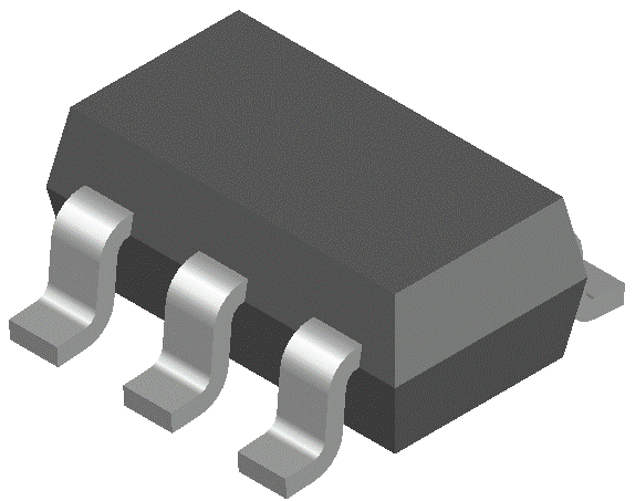
The NCP163 is a next generation of high PSRR, ultra−low noise LDO capable of supplying 250 mA output current. Designed to meet the requirements of RF and sensitive analog circuits, the NCP163 device provides ultra−low noise, high PSRR and low quiescent current. The device also offer excelent load/line transients. The NCP163 is designed to work with a 1 mF input and a 1 mF output ceramic capacitor. It is available in two thickness ultra−small 0.35P, WLCSP Packages, XDFN4 0.65P and industry standard SOT23−5L.
XXDFN4 CASE 711AJ 1 X A1 XM XX M 1 SOT23−5L CASE 527AH XXX MG G Features • Operating Input Voltage Range: 2.2 V to 5.5 V • Available in Fixed Voltage Option: 1.2 V to 5.3 V • ±2% Accuracy Over Load/Temperature • Ultra Low Quiescent Current Typ. 12 mA • Standby Current: Typ. 0.1 mA • Very Low Dropout: 80 mV at 250 mA • Ultra High PSRR: Typ. 92 dB at 20 mA, f = 1 kHz • Ultra Low Noise: 6.5 mV RMS • Stable with a 1 mF Small Case Size Ceramic Capacitors • Available in − WLCSP4: 0.64 mm x 0.64 mm x 0.33 mm X, XXX = Specific Device Code M = Date Code
(Note: Microdot may be in either location)
5 OUT 4 NC Typical Applications • Battery−powered Equipment • Wireless LAN Devices • Smartphones, Tablets • Cameras, DVRs, STB and Camcorders V IN
IN (Top View)
V OUT OUT NCP163 C IN 1 mF Ceramic EN C OUT
1 mF Ceramic ON OFF GND ORDERING INFORMATION See detailed ordering, marking and shipping information on page 18 of this data sheet.
Figure 1. Typical Application Schematics © Semiconductor Components Industries, LLC, 2016 June, 2024 − Rev. 16 1 Publication Order Number:
NCP163/D
IN EN ENABLE THERMAL LOGIC SHUTDOWN BANDGAP MOSFET REFERENCE
INTEGRATED DRIVER WITH SOFT−START CURRENT LIMIT OUT * ACTIVE DISCHARGE
Version A only EN GND
Figure 2. Simplified Schematic Block Diagram PIN FUNCTION DESCRIPTION Pin No. WLCSP4 Pin No. SOT23−5L Pin No. XDFN4 Pin Name A1 1 4 IN Input voltage supply pin A2 5 1 OUT Regulated output voltage. The output should be bypassed with small 1 mF ceramic
capacitor. B1 3 3 EN Chip enable: Applying V EN < 0.4 V disables the regulator, Pulling V EN > 1.2 V
enables the LDO.
B2 2 2 GND Common ground connection − 4 − NC Not connected. Can be tied to ground plane. − − EPAD EPAD Exposed pad. Can be tied to ground plane for better power dissipation.
Description ABSOLUTE MAXIMUM RATINGS
Symbol Value Unit Input Voltage (Note 1)
Rating
V IN −0.3 V to 6 V Output Voltage V OUT −0.3 to V IN + 0.3, max. 6 V V Chip Enable Input V CE −0.3 to 6 V V Output Short Circuit Duration t SC unlimited s Maximum Junction Temperature T J 150 °C Storage Temperature T STG −55 to 150 °C ESD Capability, Human Body Model (Note 2) ESD HBM 2000 V ESD Capability, Machine Model (Note 2) ESD MM 200 V ESD Capability, Charged Device Model (Note 2) ESD CDM 1000 V Stresses exceeding those listed in the Maximum Ratings table may damage the device. If any of these limits are exceeded, device functionality should not be assumed, damage may occur and reliability may be affected. 1. Refer to ELECTRICAL CHARACTERISTICS and APPLICATION INFORMATION for Safe Operating Area.
ESD Human Body Model tested per EIA/JESD22−A114 ESD Machine Model tested per EIA/JESD22−A115 ESD Charged Device Model tested per EIA/JESD22−C101, Field Induced Charge Model Latchup Current Maximum Rating tested per JEDEC standard: JESD78.
2 Share Feedback Your Opinion Matters
| Rating | Symbol | Value | Unit | ||||||
|---|---|---|---|---|---|---|---|---|---|
| Thermal Characteristics, WLCSP4 (Note 3), Thermal Resistance, Junction−to−Air | Thermal Characteristics, WLCSP4 (Note 3), Thermal Resistance, Junction−to−Air | Thermal Characteristics, WLCSP4 (Note 3), Thermal Resistance, Junction−to−Air | Thermal Characteristics, WLCSP4 (Note 3), Thermal Resistance, Junction−to−Air | RqJA | RqJA | 108 | 108 | 108 | °C/W |
| Thermal Characteristics, XDFN4 (Note 3), Thermal Resistance, Junction−to−Air | Thermal Characteristics, XDFN4 (Note 3), Thermal Resistance, Junction−to−Air | Thermal Characteristics, XDFN4 (Note 3), Thermal Resistance, Junction−to−Air | Thermal Characteristics, XDFN4 (Note 3), Thermal Resistance, Junction−to−Air | RqJA | RqJA | 198.1 | 198.1 | 198.1 | °C/W |
| Thermal Characteristics, SOT23−5 (Note 3), Thermal Resistance, Junction−to−Air | Thermal Characteristics, SOT23−5 (Note 3), Thermal Resistance, Junction−to−Air | Thermal Characteristics, SOT23−5 (Note 3), Thermal Resistance, Junction−to−Air | Thermal Characteristics, SOT23−5 (Note 3), Thermal Resistance, Junction−to−Air | RqJA | RqJA | 218 | 218 | 218 | °C/W |
| 3. Measured according to JEDEC board specification. Detailed description of the board can be found in JESD51−7 ELECTRICAL CHARACTERISTICS −40°C ≤ TJ ≤ 125°C; VIN = VOUT(NOM) + 1 V; IOUT = 1 mA, CIN = COUT = 1 mF, unless otherwise noted. VEN = 1.2 V. Typical values are at TJ = +25°C (Note 4). | 3. Measured according to JEDEC board specification. Detailed description of the board can be found in JESD51−7 ELECTRICAL CHARACTERISTICS −40°C ≤ TJ ≤ 125°C; VIN = VOUT(NOM) + 1 V; IOUT = 1 mA, CIN = COUT = 1 mF, unless otherwise noted. VEN = 1.2 V. Typical values are at TJ = +25°C (Note 4). | 3. Measured according to JEDEC board specification. Detailed description of the board can be found in JESD51−7 ELECTRICAL CHARACTERISTICS −40°C ≤ TJ ≤ 125°C; VIN = VOUT(NOM) + 1 V; IOUT = 1 mA, CIN = COUT = 1 mF, unless otherwise noted. VEN = 1.2 V. Typical values are at TJ = +25°C (Note 4). | 3. Measured according to JEDEC board specification. Detailed description of the board can be found in JESD51−7 ELECTRICAL CHARACTERISTICS −40°C ≤ TJ ≤ 125°C; VIN = VOUT(NOM) + 1 V; IOUT = 1 mA, CIN = COUT = 1 mF, unless otherwise noted. VEN = 1.2 V. Typical values are at TJ = +25°C (Note 4). | 3. Measured according to JEDEC board specification. Detailed description of the board can be found in JESD51−7 ELECTRICAL CHARACTERISTICS −40°C ≤ TJ ≤ 125°C; VIN = VOUT(NOM) + 1 V; IOUT = 1 mA, CIN = COUT = 1 mF, unless otherwise noted. VEN = 1.2 V. Typical values are at TJ = +25°C (Note 4). | 3. Measured according to JEDEC board specification. Detailed description of the board can be found in JESD51−7 ELECTRICAL CHARACTERISTICS −40°C ≤ TJ ≤ 125°C; VIN = VOUT(NOM) + 1 V; IOUT = 1 mA, CIN = COUT = 1 mF, unless otherwise noted. VEN = 1.2 V. Typical values are at TJ = +25°C (Note 4). | 3. Measured according to JEDEC board specification. Detailed description of the board can be found in JESD51−7 ELECTRICAL CHARACTERISTICS −40°C ≤ TJ ≤ 125°C; VIN = VOUT(NOM) + 1 V; IOUT = 1 mA, CIN = COUT = 1 mF, unless otherwise noted. VEN = 1.2 V. Typical values are at TJ = +25°C (Note 4). | 3. Measured according to JEDEC board specification. Detailed description of the board can be found in JESD51−7 ELECTRICAL CHARACTERISTICS −40°C ≤ TJ ≤ 125°C; VIN = VOUT(NOM) + 1 V; IOUT = 1 mA, CIN = COUT = 1 mF, unless otherwise noted. VEN = 1.2 V. Typical values are at TJ = +25°C (Note 4). | 3. Measured according to JEDEC board specification. Detailed description of the board can be found in JESD51−7 ELECTRICAL CHARACTERISTICS −40°C ≤ TJ ≤ 125°C; VIN = VOUT(NOM) + 1 V; IOUT = 1 mA, CIN = COUT = 1 mF, unless otherwise noted. VEN = 1.2 V. Typical values are at TJ = +25°C (Note 4). | 3. Measured according to JEDEC board specification. Detailed description of the board can be found in JESD51−7 ELECTRICAL CHARACTERISTICS −40°C ≤ TJ ≤ 125°C; VIN = VOUT(NOM) + 1 V; IOUT = 1 mA, CIN = COUT = 1 mF, unless otherwise noted. VEN = 1.2 V. Typical values are at TJ = +25°C (Note 4). |
| Parameter | Test Conditions | Test Conditions | Symbol | Symbol | Min | Min | Typ | Max | Unit |
| Operating Input Voltage | VIN | VIN | 2.2 | 2.2 | 5.5 | V | |||
| Output Voltage Accuracy | VIN = (VOUT(NOM) + 1 V) to 5.5 V0 mA ≤ IOUT ≤ 250 mA | VIN = (VOUT(NOM) + 1 V) to 5.5 V0 mA ≤ IOUT ≤ 250 mA | VOUT | VOUT | −2 | −2 | +2 | % | |
| Output Voltage Accuracy | VIN = (VOUT(NOM) + 1 V) to 5.5 V0 mA ≤ IOUT ≤ 250 mA (for VOUT < 1.8 V, XDFN4 package) | VIN = (VOUT(NOM) + 1 V) to 5.5 V0 mA ≤ IOUT ≤ 250 mA (for VOUT < 1.8 V, XDFN4 package) | VOUT | VOUT | −3 | −3 | +3 | % | |
| Output Voltage Accuracy | VIN = (VOUT(NOM) + 1 V) to 5.5 VSOT23−5L Package Only | VIN = (VOUT(NOM) + 1 V) to 5.5 VSOT23−5L Package Only | VOUT | VOUT | −2 | −2 | +2 | % | |
| Line Regulation | VOUT(NOM) + 1 V ≤ VIN ≤ 5.5 V | VOUT(NOM) + 1 V ≤ VIN ≤ 5.5 V | LineReg | LineReg | 0.02 | %/V | |||
| Load Regulation | IOUT = 1mA to 250mA | WLCSP, XDFN4 | LoadReg | LoadReg | 0.001 | %/mA | |||
| Load Regulation | IOUT = 1mA to 250mA | SOT23−5L | LoadReg | LoadReg | 0.008 | 0.015 | %/mA | ||
| Dropout Voltage (Note 5) | IOUT = 250 mA (WLCSP, XDFN4 Packages) | VOUT(NOM) = 1.8 V | VDO | VDO | 180 | 250 | mV | ||
| Dropout Voltage (Note 5) | IOUT = 250 mA (WLCSP, XDFN4 Packages) | VOUT(NOM) = 2.5 V | VDO | VDO | 110 | 175 | mV | ||
| Dropout Voltage (Note 5) | IOUT = 250 mA (WLCSP, XDFN4 Packages) | VOUT(NOM) = 2.8 V | VDO | VDO | 95 | 160 | mV | ||
| Dropout Voltage (Note 5) | IOUT = 250 mA (WLCSP, XDFN4 Packages) | VOUT(NOM) = 3.0 V | VDO | VDO | 90 | 155 | mV | ||
| Dropout Voltage (Note 5) | IOUT = 250 mA (WLCSP, XDFN4 Packages) | VOUT(NOM) = 3.2 V | VDO | VDO | 85 | 149 | mV | ||
| Dropout Voltage (Note 5) | IOUT = 250 mA (WLCSP, XDFN4 Packages) | VOUT(NOM) = 3.3 V | VDO | VDO | 80 | 145 | mV | ||
| Dropout Voltage (Note 5) | IOUT = 250 mA (WLCSP, XDFN4 Packages) | VOUT(NOM) = 3.5 V | VDO | VDO | 75 | 140 | mV | ||
| Dropout Voltage (Note 5) | IOUT = 250 mA (WLCSP, XDFN4 Packages) | VOUT(NOM) = 4.5 V | VDO | VDO | 65 | 120 | mV | ||
| Dropout Voltage (Note 5) | IOUT = 250 mA (WLCSP, XDFN4 Packages) | VOUT(NOM) = 5.0 V | VDO | VDO | 75 | 105 | mV | ||
| Dropout Voltage (Note 5) | IOUT = 250 mA (SOT23−5L Package) | VOUT(NOM) = 1.8 V | VDO | VDO | 205 | 280 | mV | ||
| Dropout Voltage (Note 5) | IOUT = 250 mA (SOT23−5L Package) | VOUT(NOM) = 2.8 V | VDO | VDO | 120 | 190 | mV | ||
| Dropout Voltage (Note 5) | IOUT = 250 mA (SOT23−5L Package) | VOUT(NOM) = 3.0 V | VDO | VDO | 115 | 185 | mV | ||
| Dropout Voltage (Note 5) | IOUT = 250 mA (SOT23−5L Package) | VOUT(NOM) = 3.3 V | VDO | VDO | 105 | 175 | mV | ||
| Output Current Limit | VOUT = 90% VOUT(NOM) | VOUT = 90% VOUT(NOM) | ICL | ICL | 250 | 250 | 700 | mA | |
| Short Circuit Current | VOUT = 0 V | VOUT = 0 V | ISC | ISC | 690 | mA | |||
| Quiescent Current | IOUT = 0 mA | IOUT = 0 mA | IQ | IQ | 12 | 20 | mA | ||
| Shutdown Current | VEN ≤ 0.4 V, VIN = 4.8 V | VEN ≤ 0.4 V, VIN = 4.8 V | IDIS | IDIS | 0.01 | 1 | mA | ||
| EN Pin Threshold Voltage | EN Input Voltage “H” | EN Input Voltage “H” | VENH | VENH | 1.2 | 1.2 | V | ||
| EN Pin Threshold Voltage | EN Input Voltage “L” | EN Input Voltage “L” | VENL | VENL | 0.4 | V | |||
| EN Pull Down Current | VEN = 4.8 V | VEN = 4.8 V | IEN | IEN | 0.2 | 0.5 | mA | ||
| Turn−On Time | COUT = 1 mF, From assertion of VEN to VOUT = 95% VOUT(NOM) | “A” Option | 120 | ms | |||||
| Turn−On Time | COUT = 1 mF, From assertion of VEN to VOUT = 95% VOUT(NOM) | “C” Option | 135 | ms | |||||
| Power Supply Rejection Ratio | IOUT = 20 mA | f = 100 Hz f = 1 kHz f = 10 kHz f = 100 kHz | PSRR | PSRR | 60 85 92 91 | dB | |||
V OUT
Line Regulation Load Regulation Dropout Voltage (Note 5)
Dropout Voltage (Note 5)
Unit 2.2 5.5 V −2 +2 −3 +3 −2 +2
mV mV
Short Circuit Current V OUT = 0 V I SC 690 Quiescent Current I OUT = 0 mA I Q 12 20 mA Shutdown Current V EN ≤ 0.4 V, V IN = 4.8 V I DIS 0.01 1 mA
EN Input Voltage “H” V ENH EN Input Voltage “L” V ENL V EN = 4.8 V I EN EN Pull Down Current Turn−On Time Power Supply Rejection Ratio C OUT = 1 mF, From assertion of V EN to
V OUT = 95% V OUT(NOM)
%/mA Output Current Limit EN Pin Threshold Voltage % %/V
Max Typ 1.2
0.4 0.2 “A” Option 120
“C” Option 135
91 92 85 60 www.onsemi.com
3 PSRR mA 0.5 V mA ms dB Share Feedback Your Opinion Matters
ELECTRICAL CHARACTERISTICS −40°C ≤ T J ≤ 125°C; V IN = V OUT(NOM) + 1 V; I OUT = 1 mA, C IN = C OUT = 1 mF, unless otherwise noted. V EN = 1.2 V. Typical values are at T J = +25°C (Note 4).
Parameter Output Voltage Noise Thermal Shutdown Threshold Active Output Discharge Resistance Line Transient (Note 6)
Test Conditions f = 10 Hz to 100 kHz I OUT = 1 mA
| Parameter | Test Conditions | Symbol | Min | Typ | Max | Unit | |
|---|---|---|---|---|---|---|---|
| Output Voltage Noise | f = 10 Hz to 100 kHz | IOUT = 1 mA IOUT = 250 mA | VN | 8.06.5 | mVRMS | ||
| Thermal Shutdown Threshold | Temperature rising | Temperature rising | TSDH | 160 | °C | ||
| Thermal Shutdown Threshold | Temperature falling | Temperature falling | TSDL | 140 | °C | ||
| Active Output Discharge Resistance | VEN < 0.4 V, Version A only | VEN < 0.4 V, Version A only | RDIS | 280 | W | ||
| Line Transient (Note 6) | VIN = (VOUT(NOM) + 1 V) to (VOUT(NOM) +1.6 V) in 30 ms, IOUT = 1 mA | VIN = (VOUT(NOM) + 1 V) to (VOUT(NOM) +1.6 V) in 30 ms, IOUT = 1 mA | TranLINE | −1 | mV | ||
| Line Transient (Note 6) | VIN = (VOUT(NOM) + 1.6 V) to (VOUT(NOM) +1 V) in 30 ms, IOUT = 1 mA | VIN = (VOUT(NOM) + 1.6 V) to (VOUT(NOM) +1 V) in 30 ms, IOUT = 1 mA | TranLINE | +1 | mV | ||
| Load Transient (Note 6) | IOUT = 1 mA to 200 mA in 10 ms | IOUT = 1 mA to 200 mA in 10 ms | TranLOAD | −40 | mV | ||
| Load Transient (Note 6) | IOUT = 200 mA to 1mA in 10 ms | IOUT = 200 mA to 1mA in 10 ms | TranLOAD | +40 | mV | ||
Load Transient (Note 6)
Symbol
−1 Tran LINE mV
+1 Tran LOAD −40
+40 mV Product parametric performance is indicated in the Electrical Characteristics for the listed test conditions, unless otherwise noted. Product performance may not be indicated by the Electrical Characteristics if operated under different conditions. 4. Performance guaranteed over the indicated operating temperature range by design and/or characterization. Production tested at T A = 25°C.
Low duty cycle pulse techniques are used during the testing to maintain the junction temperature as close to ambient as possible.
4 Share Feedback Your Opinion Matters
TYPICAL CHARACTERISTICS 3.330 V OUT , VOLTAGE (V)
3.335
3.300 3.295 3.290 3.285
−40 −20 0 20 40 60 80 100 120 140 0.05
REG LINE , LINE REGULATION (%/V)
3.305 Figure 4. Output Voltage vs. Temperature −
V OUT = 3.3 V − XDFN Package 0.04 0.03 0.02 0.01
0 −0.01
−0.02 −0.03 −0.04 −0.05
−40 −20 0 20 40 60 80 100 120 140 T J , JUNCTION TEMPERATURE (°C) T J , JUNCTION TEMPERATURE (°C) Figure 5. Output Voltage vs. Temperature −
V OUT = 5.0 V − XDFN Package Figure 6. Line Regulation vs. Temperature −
REG LOAD , LOAD REGULATION (mV)
0.050 REG , LINE REGULATION (%/V)
Figure 3. Output Voltage vs. Temperature −
V OUT = 1.8 V − XDFN Package 0.040 0.030 0.020 0.010
0 −0.010
3.315 T J , JUNCTION TEMPERATURE (°C)
3.320 T J , JUNCTION TEMPERATURE (°C)
3.325
20
18 16 14 12 10 8 6 4 2 0 −40 −20 0 20 40 60 80 100 120 140 T J , JUNCTION TEMPERATURE (°C) T J , JUNCTION TEMPERATURE (°C) Figure 7. Line Regulation vs. Temperature −
Figure 8. Load Regulation vs. Temperature −
5 Share Feedback Your Opinion Matters
REG LOAD , LOAD REGULATION (mV)
20
18 16 14 12 10 8 6 4 2 0 −40 −20 0 20 40 60 80 100 120 140 18 16 14 12 10 8 6 2 0 −40 −20 0 20 40 60 80 100 120 140
T J , JUNCTION TEMPERATURE (°C) Figure 9. Load Regulation vs. Temperature −
Figure 10. Load Regulation vs. Temperature −
1500 1500
0 100 125 150 175 200 225 250 0 25 50 75 100 125 150 175 200 225 250 I OUT , OUTPUT CURRENT (mA) I OUT , OUTPUT CURRENT (mA) Figure 11. Ground Current vs. Load Current −
Figure 12. Ground Current vs. Load Current −
VDROP ,
4 20 T J , JUNCTION TEMPERATURE (°C)
IGND , GROUND REG LOAD , LOAD REGULATION (mV)
TYPICAL CHARACTERISTICS
0 25 50 75 100 125 150 175 200 225 250 I OUT , OUTPUT CURRENT (mA) I OUT , OUTPUT CURRENT (mA) Figure 13. Ground Current vs. Load Current −
Figure 14. Dropout Voltage vs. Load Current −
6 Share Feedback Your Opinion Matters
TYPICAL CHARACTERISTICS 150 V DROP , DROPOUT VOLTAGE (mV)
VDROP , DROPOUT VOLTAGE (mV)
150 135
105
75 60 T
J = −40°C 45
30 15 0
0 25 50 75 100 125 150 175 200 225 250
15 0
0 25 50 75
100 125 150 175 200 225 250 V DROP , DROPOUT V DROP , DROPOUT VOLTAGE (mV)
Figure 16. Dropout Voltage vs. Load Current −
175
C OUT = 1 mF I OUT = 100 mA 75 50 25 0 −40 −20
0 20 40 60 80 100 120 140
60
30 15 0 −40 −20 0 20 40 60 80 100 120 140 T J , JUNCTION TEMPERATURE (°C) T J , JUNCTION TEMPERATURE (°C) Figure 17. Dropout Voltage vs. Temperature −
Figure 18. Dropout Voltage vs. Temperature −
100 720
700 I CL , CURRENT LIMIT (mA)
VDROP , DROPOUT VOLTAGE (mV)
75 Figure 15. Dropout Voltage vs. Load Current −
200 100
I OUT , OUTPUT CURRENT (mA)
225 125 120 105 I OUT , OUTPUT CURRENT (mA)
250 150 135
60
40 30
20 10 0 −40 −20 0 20 40 60 80 100 680 660 640 620 600 560 540 520 −40 −20 120 140
580 0 20 40 60 80 100 120 140 T J , JUNCTION TEMPERATURE (°C) T J , JUNCTION TEMPERATURE (°C) Figure 19. Dropout Voltage vs. Temperature −
Figure 20. Current Limit vs. Temperature www.onsemi.com
7 Share Feedback Your Opinion Matters
VEN , ENABLE VOLTAGE THRESHOLD (V) 700 680 660 640 620 600 580
560 540 520 500
−40 −20 0 20 40 60 80 100 120 140 0.9 0.8 0.7 0.6 0.4 0.2 0.1
0 −40 −20 0 20 40 60 80 100 120 140 Figure 21. Short Circuit Current vs.
Temperature Figure 22. Enable Thresholds Voltage 0.45 90 0.40 0.35 0.30 0.25 0.20
0.15 0.10 0.05
0 −40 −20
0.3 100 ON −> OFF 0.5 0.50 OFF −> ON T J , JUNCTION TEMPERATURE (°C)
0 20 40 60 80 100 120 140
80 70 60 50 40 30 20 10 0 −40 −20 0 20 40 60 80 100 120 140 T J , JUNCTION TEMPERATURE (°C) T J , JUNCTION TEMPERATURE (°C) Figure 23. Current to Enable Pin vs.
Temperature Figure 24. Disable Current vs. Temperature
RDIS , DISCHARGE RESISTIVITY 1.0 T J , JUNCTION TEMPERATURE (°C)
IDIS , DISABLE CURRENT (nA)
IEN , ENABLE PIN CURRENT (mA)
ISC , SHORT CIRCUIT CURRENT (mA)
TYPICAL CHARACTERISTICS T J , JUNCTION TEMPERATURE (°C) I OUT , OUTPUT CURRENT (mA) Figure 25. Discharge Resistance vs.
Temperature Figure 26. Maximum C OUT ESR Value vs. Load
Current www.onsemi.com
8 Share Feedback Your Opinion Matters
TYPICAL CHARACTERISTICS OUTPUT NOISE (nV/√Hz)
10K
1 mA 10 mA 250 mA 1K 100 10 1 RMS Output Noise (mV) 10 Hz − 100 kHz 100 Hz − 100 kHz I OUT 1 mA 7.73 6.99 10 mA 7.12 6.26 250 mA 7.11 6.33
10 100 1K 10K 1M 100K
FREQUENCY (Hz)
Figure 27. Output Voltage Noise Spectral Density – V OUT = 1.8 V OUTPUT NOISE (nV/√Hz)
10K
1 mA 10 mA 250 mA 1K 100 10 1 RMS Output Noise (mV) 10 Hz − 100 kHz 100 Hz − 100 kHz I OUT 1 mA 7.9 7.07 10 mA 7.19 6.25 250 mA 7.29 6.38
10 100 1K 10K 1M 100K
FREQUENCY (Hz)
Figure 28. Output Voltage Noise Spectral Density – V OUT = 2.8 V
C OUT = 1 mF MLCC 1206 100 RR, RIPPLE REJECTION (dB)
RR, RIPPLE REJECTION (dB)
120 80 60 40 1 mA
10 mA 20 mA 100 mA 250 mA 20 0 10 100 1K 10K 100K 1M 100 80 60 1 mA 10 mA 20 mA 100 mA 250 mA 40 20 0 10M
C OUT = 1 mF MLCC 1206 10 100 1K 10K 100K 1M FREQUENCY (Hz) FREQUENCY (Hz) Figure 29. Power Supply Rejection Ratio −
Figure 30. Power Supply Rejection Ratio −
9 10M Share Feedback Your Opinion Matters
TYPICAL CHARACTERISTICS RR, RIPPLE REJECTION (dB)
120 100 80 60 1 mA 10 mA 20 mA 100 mA 250 mA 40 20 0
10 100
C OUT = 1 mF MLCC 1206 1K 10K 100K 1M 10M FREQUENCY (Hz)
50 ms/div Figure 33. Enable Turn−on Response − C OUT = 4.7 mF, I OUT = 10 mA − “A” Option 500 mV/div 50 ms/div Figure 32. Enable Turn−on Response − C OUT = 1 mF, I OUT = 10 mA − “A” Option
| mV/div | mV/div | ||||
|---|---|---|---|---|---|
| 500 | VEN | 500 | VEN | ||
| VIN = 4.3 V | |||||
| 1 V/div | VOUT | VOUT = 3.3 V COUT = 1 mF (MLCC) | V/div | VOUT | VIN = 4.3 VVOUT = 3.3 V |
| 1 | COUT = 4.7 mF (MLCC) | ||||
| 200 mA/div | IINPUT | 200 mA/div | IINPUT | ||
50 ms/div 50 ms/div Figure 34. Enable Turn−on Response − C OUT = 1 mF, I OUT = 250 mA − “A” Option Figure 35. Enable Turn−on Response − C OUT = 4.7 mF, I OUT = 250 mA − “A” Option www.onsemi.com
10 Share Feedback Your Opinion Matters
50 ms/div 50 ms/div Figure 36. Enable Turn−on Response −
C OUT = 1 mF − “A” Option − Normal Figure 37. Enable Turn−on Response −
C OUT = 1 mF − “C” Option − Slow www.onsemi.com
11 Share Feedback Your Opinion Matters
TYPICAL CHARACTERISTICS 500 mV/div 10 mV/div
2 ms/div 2 ms/div Figure 38. Line Transient Response −
Figure 39. Line Transient Response −
10 mV/div mV/div
2 ms/div 2 ms/div Figure 40. Line Transient Response −
Figure 41. Line Transient Response −
5 ms/div 10 ms/div Figure 42. Load Transient Response −
1 mA to 250 mA Figure 43. Load Transient Response −
250 mA to 1 mA www.onsemi.com
12 Share Feedback Your Opinion Matters
TYPICAL CHARACTERISTICS
5 ms/div 5 ms/div Figure 44. Load Transient Response −
1 mA to 250 mA Figure 45. Load Transient Response −
250 mA to 1 mA 1 V/div
400 ms/div Figure 48. Enable Turn−off − Various Output
Capacitors www.onsemi.com
13 Share Feedback Your Opinion Matters
APPLICATIONS INFORMATION
General transient response or high frequency PSRR. It is not
recommended to use tantalum capacitors on the output due to their large ESR. The equivalent series resistance of tantalum capacitors is also strongly dependent on the temperature, increasing at low temperature.
The NCP163 is an ultra−low noise 250 mA low dropout regulator designed to meet the requirements of RF applications and high performance analog circuits. The NCP163 device provides very high PSRR and excellent dynamic response. In connection with low quiescent current this device is well suitable for battery powered application such as cell phones, tablets and other. The NCP163 is fully protected in case of current overload, output short circuit and overheating.
Enable Operation
The NCP163 uses the EN pin to enable/disable its device and to deactivate/activate the active discharge function.
If the EN pin voltage is <0.4 V the device is guaranteed to be disabled. The pass transistor is turned−off so that there is virtually no current flow between the IN and OUT. The active discharge transistor is active so that the output voltage V OUT is pulled to GND through a 280 W resistor. In the disable state the device consumes as low as typ. 10 nA from the V IN .
If the EN pin voltage >1.2 V the device is guaranteed to be enabled. The NCP163 regulates the output voltage and the active discharge transistor is turned−off.
The EN pin has internal pull−down current source with typ. value of 200 nA which assures that the device is turned−off when the EN pin is not connected. In the case where the EN function isn’t required the EN should be tied directly to IN.
The NCP163 provides soft−start feature ensures smooth monotonous output voltage rising. It prevents excessive input current after EN pin turn−on when big output capacitance is connected.
There are two slew−rate options of start−up ramp. The normal ”A” option and slower ”C” option. For more information please refer ordering information table.
Input Capacitor Selection (C IN )
Input capacitor connected as close as possible is necessary for ensure device stability. The X7R or X5R capacitor should be used for reliable performance over temperature range. The value of the input capacitor should be 1 mF or greater to ensure the best dynamic performance. This capacitor will provide a low impedance path for unwanted AC signals or noise modulated onto constant input voltage. There is no requirement for the ESR of the input capacitor but it is recommended to use ceramic capacitors for their low ESR and ESL. A good input capacitor will limit the influence of input trace inductance and source resistance during sudden load current changes.
Output Decoupling (C OUT )
The NCP163 requires an output capacitor connected as close as possible to the output pin of the regulator. The recommended capacitor value is 1 mF and X7R or X5R dielectric due to its low capacitance variations over the specified temperature range. The NCP163 is designed to remain stable with minimum effective capacitance of 0.7 mF to account for changes with temperature, DC bias and package size. Especially for small package size capacitors such as 0201 the effective capacitance drops rapidly with the
14 Share Feedback Your Opinion Matters
Power Dissipation
The power dissipated by the NCP163 for given application conditions can be calculated from the following equations:
P D [ V IN @ I GND ) I OUT ǒ V IN * V OUT Ǔ
(eq. 2)
120 0.8 q JA , 1 oz Cu 110 0.6 0.4 100 q JA , 2 oz Cu 90 80 (eq. 1)
0 100 200 300 400 500 0.2 600 P D(MAX)
, MAXIMUM POWER q JA , JUNCTION TO AMBIENT THERMAL As power dissipated in the NCP163 increases, it might become necessary to provide some thermal relief. The maximum power dissipation supported by the device is dependent upon board design and layout. Mounting pad configuration on the PCB, the board material, and the ambient temperature affect the rate of junction temperature rise for the part.
The maximum power dissipation the NCP163 can handle is given by:
0 700 PCB COPPER AREA (mm 2 ) Figure 50. q JA and P D (MAX) vs. Copper Area (CSP4)
15 Share Feedback Your Opinion Matters 220 1.0
q JA , 1 oz Cu 210 0.9
160 0.4 150
0 100 200 300 400
PCB COPPER AREA (mm 2 )
500 600 P , MAXIMUM POWER DISSIPATION (W)
qJA , JUNCTION RESISTANCE (°C/W)
0.3 700 0.7 325
300
275 250 0.6 0.5 0.4 q JA , 1 oz Cu 225 0.3 q JA , 2 oz Cu 200 0.2 175 150 0.1 0 100 200 300 400
PCB COPPER AREA (mm 2 )
500 600 P D(MAX)
, MAXIMUM POWER DISSIPATION (W)
qJA , JUNCTION TO AMBIENT THERMAL RESISTANCE (°C/W)
Figure 51. q JA and P D (MAX) vs. Copper Area (XDFN4)
0 700 Figure 52. q JA and P D (MAX) vs. Copper Area (SOT23−5L)
16 Share Feedback Your Opinion Matters
Reverse Current Turn−On Time
The PMOS pass transistor has an inherent body diode which will be forward biased in the case that V OUT > V IN . Due to this fact in cases, where the extended reverse current condition can be anticipated the device may require additional external protection.
The turn−on time is defined as the time period from EN assertion to the point in which V OUT will reach 98% of its nominal value. This time is dependent on various application conditions such as V OUT(NOM) , C OUT , T A .
Power Supply Rejection Ratio To obtain good transient performance and good regulation
characteristics place C IN and C OUT capacitors close to the device pins and make the PCB traces wide. In order to minimize the solution size, use 0402 or 0201 capacitors with appropriate capacity. Larger copper area connected to the pins will also improve the device thermal resistance. The actual power dissipation can be calculated from the equation above (Equation 2). Expose pad can be tied to the GND pin for improvement power dissipation and lower device temperature.
PCB Layout Recommendations
The NCP163 features very high Power Supply Rejection ratio. If desired the PSRR at higher frequencies in the range 100 kHz – 10 MHz can be tuned by the selection of C OUT capacitor and proper PCB layout.
17 Share Feedback Your Opinion Matters
ORDERING INFORMATION (WLCSP4)
| Device | Voltage Option | Marking | Rotation | Description | Package | Shipping† |
|---|---|---|---|---|---|---|
| NCP163AFCS120T2G | 1.2 V | 2 | 0 | 250 mA, Active Discharge | WLCSP4 CASE 567KA (Pb-Free) | 5000 / Tape & Reel |
| NCP163AFCS180T2G | 1.8 V | Y | 180 | 250 mA, Active Discharge | WLCSP4 CASE 567KA (Pb-Free) | 5000 / Tape & Reel |
| NCP163AFCS250T2G | 2.5 V | T | 270 | 250 mA, Active Discharge | WLCSP4 CASE 567KA (Pb-Free) | 5000 / Tape & Reel |
| NCP163AFCS260T2G | 2.6 V | 4 | 180 | 250 mA, Active Discharge | WLCSP4 CASE 567KA (Pb-Free) | 5000 / Tape & Reel |
| NCP163AFCS270T2G | 2.7 V | V | 270 | 250 mA, Active Discharge | WLCSP4 CASE 567KA (Pb-Free) | 5000 / Tape & Reel |
| NCP163AFCS280T2G | 2.8 V | 3 | 180 | 250 mA, Active Discharge | WLCSP4 CASE 567KA (Pb-Free) | 5000 / Tape & Reel |
| NCP163AFCS285T2G | 2.85 V | 5 | 180 | 250 mA, Active Discharge | WLCSP4 CASE 567KA (Pb-Free) | 5000 / Tape & Reel |
| NCP163AFCS290T2G | 2.9 V | 6 | 180 | 250 mA, Active Discharge | WLCSP4 CASE 567KA (Pb-Free) | 5000 / Tape & Reel |
| NCP163AFCS2925T2G | 2.925 V | 2 | 180 | 250 mA, Active Discharge | WLCSP4 CASE 567KA (Pb-Free) | 5000 / Tape & Reel |
| NCP163BFCS180T2G | 1.8 V | Y | 270 | 250 mA, Non−Active Discharge | WLCSP4 CASE 567KA (Pb-Free) | 5000 / Tape & Reel |
| NCP163BFCS2925T2G | 2.925 V | 2 | 270 | 250 mA, Non−Active Discharge | WLCSP4 CASE 567KA (Pb-Free) | 5000 / Tape & Reel |
| NCP163CFCS285T2G | 2.85 V | P | 180 | 250 mA, Active Discharge Slow Turn−On Slew | WLCSP4 CASE 567XW (Pb-Free) | 10000 / Tape & Reel |
| NCP163AFCT120T2G | 1.2 V | A | 0 | 250 mA, Active Discharge | WLCSP4 CASE 567JZ (Pb-Free) | 5000 or 10000 / Tape & Reel (Note 7) |
| NCP163AFCT180T2G | 1.8 V | Y | 180 | 250 mA, Active Discharge | WLCSP4 CASE 567JZ (Pb-Free) | 5000 or 10000 / Tape & Reel (Note 7) |
| NCP163AFCT250T2G | 2.5 V | Y | 90 | 250 mA, Active Discharge | WLCSP4 CASE 567JZ (Pb-Free) | 5000 or 10000 / Tape & Reel (Note 7) |
| NCP163AFCT260T2G | 2.6 V | 6 | 270 | 250 mA, Active Discharge | WLCSP4 CASE 567JZ (Pb-Free) | 5000 or 10000 / Tape & Reel (Note 7) |
| NCP163AFCT270T2G | 2.7 V | 5 | 180 | 250 mA, Active Discharge | WLCSP4 CASE 567JZ (Pb-Free) | 5000 or 10000 / Tape & Reel (Note 7) |
| NCP163AFCT280T2G | 2.8 V | 3 | 180 | 250 mA, Active Discharge | WLCSP4 CASE 567JZ (Pb-Free) | 5000 or 10000 / Tape & Reel (Note 7) |
| NCP163AFCT285T2G | 2.85 V | 5 | 270 | 250 mA, Active Discharge | WLCSP4 CASE 567JZ (Pb-Free) | 5000 or 10000 / Tape & Reel (Note 7) |
| NCP163AFCT290T2G | 2.9 V | 4 | 270 | 250 mA, Active Discharge | WLCSP4 CASE 567JZ (Pb-Free) | 5000 or 10000 / Tape & Reel (Note 7) |
| NCP163AFCT2925T2G | 2.925 V | 2 | 180 | 250 mA, Active Discharge | WLCSP4 CASE 567JZ (Pb-Free) | 5000 or 10000 / Tape & Reel (Note 7) |
| NCP163AFCT300T2G | 3.0 V | 3 | 270 | 250 mA, Active Discharge | WLCSP4 CASE 567JZ (Pb-Free) | 5000 or 10000 / Tape & Reel (Note 7) |
| NCP163AFCT330T2G | 3.3 V | 6 | 90 | 250 mA, Active Discharge | WLCSP4 CASE 567JZ (Pb-Free) | 5000 or 10000 / Tape & Reel (Note 7) |
| NCP163BFCT180T2G | 1.8 V | Y | 270 | 250 mA, Non−Active Discharge | WLCSP4 CASE 567JZ (Pb-Free) | 5000 or 10000 / Tape & Reel (Note 7) |
| NCP163BFCT2925T2G | 2.925 V | 2 | 270 | 250 mA, Non−Active Discharge | WLCSP4 CASE 567JZ (Pb-Free) | 5000 or 10000 / Tape & Reel (Note 7) |
Slow Turn−On Slew 250 mA, Active Discharge 250 mA, Non−Active Discharge †For information on tape and reel specifications, including part orientation and tape sizes, please refer to our Tape and Reel Packaging Specifications Brochure, BRD8011/D. 7. Product processed after April 1, 2023 are shipped with quantity 10000 units / tape & reel.
18 Share Feedback Your Opinion Matters
| Device | Voltage Option | Marking | Description | Package | Shipping† | |||
|---|---|---|---|---|---|---|---|---|
| NCP163AMX120TBG* (Note 8) | 1.2 V | ME | 250 mA, Active Discharge | XDFN4 CASE 711AJ (Pb-Free) | 3000 or 5000 / Tape & Reel (Note 8) | |||
| NCP163AMX130TBG* (Note 8) | 1.3 V | MG | 250 mA, Active Discharge | XDFN4 CASE 711AJ (Pb-Free) | 3000 or 5000 / Tape & Reel (Note 8) | |||
| NCP163AMX150TBG | 1.5 V | MV | 250 mA, Active Discharge | XDFN4 CASE 711AJ (Pb-Free) | 3000 or 5000 / Tape & Reel (Note 8) | |||
| NCP163AMX180TBG (Note 8) | NCP163AMX180TBG (Note 8) | 1.8 V | 1.8 V | MA | MA | 250 mA, Active Discharge | XDFN4 CASE 711AJ (Pb-Free) | 3000 or 5000 / Tape & Reel (Note 8) |
| NCP163AMX1825TBG (Note 8) | NCP163AMX1825TBG (Note 8) | 1.825 V | 1.825 V | MC | MC | 250 mA, Active Discharge | XDFN4 CASE 711AJ (Pb-Free) | 3000 or 5000 / Tape & Reel (Note 8) |
| NCP163AMX185TBG (In Development) | NCP163AMX185TBG (In Development) | 1.85 V | 1.85 V | MZ | MZ | 250 mA, Active Discharge | XDFN4 CASE 711AJ (Pb-Free) | 3000 or 5000 / Tape & Reel (Note 8) |
| NCP163AMX190TBG | NCP163AMX190TBG | 1.9 V | 1.9 V | MH | MH | 250 mA, Active Discharge | XDFN4 CASE 711AJ (Pb-Free) | 3000 or 5000 / Tape & Reel (Note 8) |
| NCP163AMX250TBG | NCP163AMX250TBG | 2.5 V | 2.5 V | MU | MU | 250 mA, Active Discharge | XDFN4 CASE 711AJ (Pb-Free) | 3000 or 5000 / Tape & Reel (Note 8) |
| NCP163AMX260TBG | NCP163AMX260TBG | 2.6 V | 2.6 V | MN | MN | 250 mA, Active Discharge | XDFN4 CASE 711AJ (Pb-Free) | 3000 or 5000 / Tape & Reel (Note 8) |
| NCP163AMX270TBG (Note 8) | NCP163AMX270TBG (Note 8) | 2.7 V | 2.7 V | MX | MX | 250 mA, Active Discharge | XDFN4 CASE 711AJ (Pb-Free) | 3000 or 5000 / Tape & Reel (Note 8) |
| NCP163AMX275TBG | NCP163AMX275TBG | 2.75 V | 2.75 V | MD | MD | 250 mA, Active Discharge | XDFN4 CASE 711AJ (Pb-Free) | 3000 or 5000 / Tape & Reel (Note 8) |
| NCP163AMX280TBG (Note 8) | NCP163AMX280TBG (Note 8) | 2.8 V | 2.8 V | MM | MM | 250 mA, Active Discharge | XDFN4 CASE 711AJ (Pb-Free) | 3000 or 5000 / Tape & Reel (Note 8) |
| NCP163AMX285TBG | NCP163AMX285TBG | 2.85 V | 2.85 V | MQ | MQ | 250 mA, Active Discharge | XDFN4 CASE 711AJ (Pb-Free) | 3000 or 5000 / Tape & Reel (Note 8) |
| NCP163AMX290TBG (Note 8) | NCP163AMX290TBG (Note 8) | 2.9 V | 2.9 V | MR | MR | 250 mA, Active Discharge | XDFN4 CASE 711AJ (Pb-Free) | 3000 or 5000 / Tape & Reel (Note 8) |
| NCP163AMX300TBG (Note 8) | NCP163AMX300TBG (Note 8) | 3.0 V | 3.0 V | MJ | MJ | 250 mA, Active Discharge | XDFN4 CASE 711AJ (Pb-Free) | 3000 or 5000 / Tape & Reel (Note 8) |
| NCP163AMX330TBG (Note 8) | NCP163AMX330TBG (Note 8) | 3.3 V | 3.3 V | MK | MK | 250 mA, Active Discharge | XDFN4 CASE 711AJ (Pb-Free) | 3000 or 5000 / Tape & Reel (Note 8) |
| NCP163AMX500TBG (Note 8) | NCP163AMX500TBG (Note 8) | 5.0 V | 5.0 V | ML | ML | 250 mA, Active Discharge | XDFN4 CASE 711AJ (Pb-Free) | 3000 or 5000 / Tape & Reel (Note 8) |
| NCP163BMX180TBG (Note 8) | NCP163BMX180TBG (Note 8) | 1.8 V | 1.8 V | PA | PA | 250 mA, Non−Active Discharge | XDFN4 CASE 711AJ (Pb-Free) | 3000 or 5000 / Tape & Reel (Note 8) |
| NCP163BMX1825TBG (Note 8) | NCP163BMX1825TBG (Note 8) | 1.825 V | 1.825 V | PC | PC | 250 mA, Non−Active Discharge | XDFN4 CASE 711AJ (Pb-Free) | 3000 or 5000 / Tape & Reel (Note 8) |
| NCP163BMX275TBG | NCP163BMX275TBG | 2.75 V | 2.75 V | PD | PD | 250 mA, Non−Active Discharge | XDFN4 CASE 711AJ (Pb-Free) | 3000 or 5000 / Tape & Reel (Note 8) |
| †For information on tape and reel specifications, including part orientation and tape sizes, please refer to our Tape and Reel Packaging Specifications Brochure, BRD8011/D. *Contact sales office for availability information. 8. Product processed after October 1, 2022 are shipped with quantity 5000 units / tape & reel. ORDERING INFORMATION (SOT23−5L) | †For information on tape and reel specifications, including part orientation and tape sizes, please refer to our Tape and Reel Packaging Specifications Brochure, BRD8011/D. *Contact sales office for availability information. 8. Product processed after October 1, 2022 are shipped with quantity 5000 units / tape & reel. ORDERING INFORMATION (SOT23−5L) | †For information on tape and reel specifications, including part orientation and tape sizes, please refer to our Tape and Reel Packaging Specifications Brochure, BRD8011/D. *Contact sales office for availability information. 8. Product processed after October 1, 2022 are shipped with quantity 5000 units / tape & reel. ORDERING INFORMATION (SOT23−5L) | †For information on tape and reel specifications, including part orientation and tape sizes, please refer to our Tape and Reel Packaging Specifications Brochure, BRD8011/D. *Contact sales office for availability information. 8. Product processed after October 1, 2022 are shipped with quantity 5000 units / tape & reel. ORDERING INFORMATION (SOT23−5L) | †For information on tape and reel specifications, including part orientation and tape sizes, please refer to our Tape and Reel Packaging Specifications Brochure, BRD8011/D. *Contact sales office for availability information. 8. Product processed after October 1, 2022 are shipped with quantity 5000 units / tape & reel. ORDERING INFORMATION (SOT23−5L) | †For information on tape and reel specifications, including part orientation and tape sizes, please refer to our Tape and Reel Packaging Specifications Brochure, BRD8011/D. *Contact sales office for availability information. 8. Product processed after October 1, 2022 are shipped with quantity 5000 units / tape & reel. ORDERING INFORMATION (SOT23−5L) | †For information on tape and reel specifications, including part orientation and tape sizes, please refer to our Tape and Reel Packaging Specifications Brochure, BRD8011/D. *Contact sales office for availability information. 8. Product processed after October 1, 2022 are shipped with quantity 5000 units / tape & reel. ORDERING INFORMATION (SOT23−5L) | †For information on tape and reel specifications, including part orientation and tape sizes, please refer to our Tape and Reel Packaging Specifications Brochure, BRD8011/D. *Contact sales office for availability information. 8. Product processed after October 1, 2022 are shipped with quantity 5000 units / tape & reel. ORDERING INFORMATION (SOT23−5L) | †For information on tape and reel specifications, including part orientation and tape sizes, please refer to our Tape and Reel Packaging Specifications Brochure, BRD8011/D. *Contact sales office for availability information. 8. Product processed after October 1, 2022 are shipped with quantity 5000 units / tape & reel. ORDERING INFORMATION (SOT23−5L) |
| Device | Voltage Option | Voltage Option | Marking | Marking | Description | Description | Package | Shipping† |
| NCP163ASN150T1G | 1.5 V | 1.5 V | KAK | KAK | 250 mA, Active Discharge | 250 mA, Active Discharge | SOT23−5LCASE 527AH (Pb-Free) | 3000 / Tape & Reel |
| NCP163ASN180T1G | 1.8 V | 1.8 V | KAA | KAA | 250 mA, Active Discharge | 250 mA, Active Discharge | SOT23−5LCASE 527AH (Pb-Free) | 3000 / Tape & Reel |
| NCP163ASN250T1G | 2.5 V | 2.5 V | KAD | KAD | 250 mA, Active Discharge | 250 mA, Active Discharge | SOT23−5LCASE 527AH (Pb-Free) | 3000 / Tape & Reel |
| NCP163ASN270T1G | 2.7 V | 2.7 V | KAL | KAL | 250 mA, Active Discharge | 250 mA, Active Discharge | SOT23−5LCASE 527AH (Pb-Free) | 3000 / Tape & Reel |
| NCP163ASN280T1G | 2.8 V | 2.8 V | KAE | KAE | 250 mA, Active Discharge | 250 mA, Active Discharge | SOT23−5LCASE 527AH (Pb-Free) | 3000 / Tape & Reel |
| NCP163ASN300T1G | 3.0 V | 3.0 V | KAF | KAF | 250 mA, Active Discharge | 250 mA, Active Discharge | SOT23−5LCASE 527AH (Pb-Free) | 3000 / Tape & Reel |
| NCP163ASN330T1G | 3.3 V | 3.3 V | KAG | KAG | 250 mA, Active Discharge | 250 mA, Active Discharge | SOT23−5LCASE 527AH (Pb-Free) | 3000 / Tape & Reel |
| NCP163ASN350T1G | 3.5 V | 3.5 V | KAH | KAH | 250 mA, Active Discharge | 250 mA, Active Discharge | SOT23−5LCASE 527AH (Pb-Free) | 3000 / Tape & Reel |
| NCP163ASN500T1G | 5.0 V | 5.0 V | KAJ | KAJ | 250 mA, Active Discharge | 250 mA, Active Discharge | SOT23−5LCASE 527AH (Pb-Free) | 3000 / Tape & Reel |
19 Share Feedback Your Opinion Matters
PACKAGE DIMENSIONS SOT−23, 5 Lead
CASE 527AH
ISSUE A
DATE 09 JUN 2021 q q q q q q1
q2 GENERIC MARKING DIAGRAM* XXXM XXX = Specific Device Code M = Date Code
*This information is generic. Please refer to device data sheet for actual part marking. Pb−Free indicator, “G” or microdot “G”, may or may not be present. Some products may not follow the Generic Marking.
DOCUMENT NUMBER:
DESCRIPTION:
98AON34320E SOT−23, 5 LEAD Electronic versions are uncontrolled except when accessed directly from the Document Repository. Printed versions are uncontrolled except when stamped “CONTROLLED COPY” in red.
PAGE 1 OF 1 onsemi and are trademarks of Semiconductor Components Industries, LLC dba onsemi or its subsidiaries in the United States and/or other countries. onsemi reserves the right to make changes without further notice to any products herein. onsemi makes no warranty, representation or guarantee regarding the suitability of its products for any particular purpose, nor does onsemi assume any liability arising out of the application or use of any product or circuit, and specifically disclaims any and all liability, including without limitation special, consequential or incidental damages. onsemi does not convey any license under its patent rights nor the rights of others.
© Semiconductor Components Industries, LLC, 2008 www.onsemi.com
PACKAGE DIMENSIONS WLCSP4, 0.64x0.64x0.33
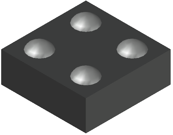
CASE 567JZ
ISSUE B
DATE 16 MAY 2022 GENERIC MARKING DIAGRAM* XM X M = Specific Device Code = Date Code
*This information is generic. Please refer to device data sheet for actual part marking. Pb−Free indicator, “G” or microdot “G”, may or may not be present. Some products may not follow the Generic Marking.
DOCUMENT NUMBER:
DESCRIPTION:
98AON85781F WLCSP4, 0.64X0.64x0.33 Electronic versions are uncontrolled except when accessed directly from the Document Repository. Printed versions are uncontrolled except when stamped “CONTROLLED COPY” in red.
PAGE 1 OF 1 onsemi and are trademarks of Semiconductor Components Industries, LLC dba onsemi or its subsidiaries in the United States and/or other countries. onsemi reserves the right to make changes without further notice to any products herein. onsemi makes no warranty, representation or guarantee regarding the suitability of its products for any particular purpose, nor does onsemi assume any liability arising out of the application or use of any product or circuit, and specifically disclaims any and all liability, including without limitation special, consequential or incidental damages. onsemi does not convey any license under its patent rights nor the rights of others.
© Semiconductor Components Industries, LLC, 2014 www.onsemi.com
PACKAGE DIMENSIONS WLCSP4, 0.64x0.64
CASE 567KA ISSUE B SCALE 4:1
DATE 24 MAR 2020 GENERIC MARKING DIAGRAM* XM X M = Specific Device Code = Date Code *This information is generic. Please refer to device data sheet for actual part marking. Pb−Free indicator, “G” or microdot “G”, may or may not be present. Some products may not follow the Generic Marking.
DOCUMENT NUMBER:
DESCRIPTION:
98AON85783F WLCSP4, 0.64X0.64 Electronic versions are uncontrolled except when accessed directly from the Document Repository. Printed versions are uncontrolled except when stamped “CONTROLLED COPY” in red.
PAGE 1 OF 1 onsemi and are trademarks of Semiconductor Components Industries, LLC dba onsemi or its subsidiaries in the United States and/or other countries. onsemi reserves the right to make changes without further notice to any products herein. onsemi makes no warranty, representation or guarantee regarding the suitability of its products for any particular purpose, nor does onsemi assume any liability arising out of the application or use of any product or circuit, and specifically disclaims any and all liability, including without limitation special, consequential or incidental damages. onsemi does not convey any license under its patent rights nor the rights of others.
© Semiconductor Components Industries, LLC, 2014 www.onsemi.com
PACKAGE DIMENSIONS WLCSP4, 0.64x0.64x0.40
CASE 567XW
ISSUE A
DATE 13 NOV 2019 GENERIC MARKING DIAGRAM* XM X M = Specific Device Code = Month
*This information is generic. Please refer to device data sheet for actual part marking. Pb−Free indicator, “G” or microdot “G”, may or may not be present. Some products may not follow the Generic Marking.
DOCUMENT NUMBER:
DESCRIPTION:
98AON08375H WLCSP4, 0.64x0.64x0.40 Electronic versions are uncontrolled except when accessed directly from the Document Repository. Printed versions are uncontrolled except when stamped “CONTROLLED COPY” in red.
PAGE 1 OF 1 onsemi and are trademarks of Semiconductor Components Industries, LLC dba onsemi or its subsidiaries in the United States and/or other countries. onsemi reserves the right to make changes without further notice to any products herein. onsemi makes no warranty, representation or guarantee regarding the suitability of its products for any particular purpose, nor does onsemi assume any liability arising out of the application or use of any product or circuit, and specifically disclaims any and all liability, including without limitation special, consequential or incidental damages. onsemi does not convey any license under its patent rights nor the rights of others.
© Semiconductor Components Industries, LLC, 2018 www.onsemi.com
PACKAGE DIMENSIONS XDFN4 1.0x1.0, 0.65P
CASE 711AJ
ISSUE C GENERIC MARKING DIAGRAM* XX M 1 DOCUMENT NUMBER:
DESCRIPTION:
XX = Specific Device Code M = Date Code 98AON67179E XDFN4, 1.0X1.0, 0.65P DATE 08 MAR 2022 *This information is generic. Please refer to device data sheet for actual part marking. Pb−Free indicator, “G” or microdot “G”, may or may not be present. Some products may not follow the Generic Marking.
Electronic versions are uncontrolled except when accessed directly from the Document Repository. Printed versions are uncontrolled except when stamped “CONTROLLED COPY” in red.
PAGE 1 OF 1 onsemi and are trademarks of Semiconductor Components Industries, LLC dba onsemi or its subsidiaries in the United States and/or other countries. onsemi reserves the right to make changes without further notice to any products herein. onsemi makes no warranty, representation or guarantee regarding the suitability of its products for any particular purpose, nor does onsemi assume any liability arising out of the application or use of any product or circuit, and specifically disclaims any and all liability, including without limitation special, consequential or incidental damages. onsemi does not convey any license under its patent rights nor the rights of others.
© Semiconductor Components Industries, LLC, 2012 www.onsemi.com onsemi, , and other names, marks, and brands are registered and/or common law trademarks of Semiconductor Components Industries, LLC dba “onsemi” or its affiliates and/or subsidiaries in the United States and/or other countries. onsemi owns the rights to a number of patents, trademarks, copyrights, trade secrets, and other intellectual property. A listing of onsemi’s product/patent coverage may be accessed at www.onsemi.com/site/pdf/Patent−Marking.pdf. onsemi reserves the right to make changes at any time to any products or information herein, without notice. The information herein is provided “as−is” and onsemi makes no warranty, representation or guarantee regarding the accuracy of the information, product features, availability, functionality, or suitability of its products for any particular purpose, nor does onsemi assume any liability arising out of the application or use of any product or circuit, and specifically disclaims any and all liability, including without limitation special, consequential or incidental damages. Buyer is responsible for its products and applications using onsemi products, including compliance with all laws, regulations and safety requirements or standards, regardless of any support or applications information provided by onsemi. “Typical” parameters which may be provided in onsemi data sheets and/or specifications can and do vary in different applications and actual performance may vary over time. All operating parameters, including “Typicals” must be validated for each customer application by customer’s technical experts. onsemi does not convey any license under any of its intellectual property rights nor the rights of others. onsemi products are not designed, intended, or authorized for use as a critical component in life support systems or any FDA Class 3 medical devices or medical devices with a same or similar classification in a foreign jurisdiction or any devices intended for implantation in the human body. Should Buyer purchase or use onsemi products for any such unintended or unauthorized application, Buyer shall indemnify and hold onsemi and its officers, employees, subsidiaries, affiliates, and distributors harmless against all claims, costs, damages, and expenses, and reasonable attorney fees arising out of, directly or indirectly, any claim of personal injury or death associated with such unintended or unauthorized use, even if such claim alleges that onsemi was negligent regarding the design or manufacture of the part. onsemi is an Equal Opportunity/Affirmative Action Employer. This literature is subject to all applicable copyright laws and is not for resale in any manner.
ADDITIONAL INFORMATION
TECHNICAL PUBLICATIONS: Technical Library: www.onsemi.com/design/resources/technical−documentation onsemi Website: www.onsemi.com ONLINE SUPPORT: www.onsemi.com/support For additional information, please contact your local Sales Representative at www.onsemi.com/support/sales